Electro Tech is an online community (with over 170,000 members) who enjoy talking about and building electronic circuits, projects and gadgets. To participate you need to register. Registration is free. Click here to register now.
Welcome to our site! Electro Tech is an online community (with over 170,000 members) who enjoy talking about and building electronic circuits, projects and gadgets. To participate you need to register. Registration is free. Click here to register now.
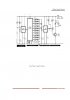
The 555 on the left is simply a monostable to debounce the switch and give a single clean clock pulse to the 4017.
The 4017 is a decade Johnson counter having a single output high at a time; the output is advanced each time you push the switch. At the 10 outputs of the 4017 are 10 variable resistors; when an output of the 4017 is high, current flows through it's associated variable resistor to charge the cap on the second 555 timer. This timer provides a constant on time (off time varies based on the value of the variable resistor) to the output motor through the current buffer transistors.
Varying the ratio of on time to off time changes the power to the motor and therefore its speed; see PWM for more info.
The very old circuit from that awful website in India does not control the speed of the wiper motor.
Instead it controls how long the wiper motor runs from nearly no time to about 10 seconds depending on the setting of the trimpot that the counter stops on.
The off-time of the motor for each cycle of its output 555 oscillator is about 5 seconds.
No it is not. That terrible website has many circuits that do not work.
Look at the datasheet of a 555. With the parts values on that horrible schematic the motor simply turns on and off at almost full speed with various durations. The speed of the motor is not controlled.
This site uses cookies to help personalise content, tailor your experience and to keep you logged in if you register.
By continuing to use this site, you are consenting to our use of cookies.