Continue to Site

Welcome to our site!

Electro Tech is an online community (with over 170,000 members) who enjoy talking about and building electronic circuits, projects and gadgets. To participate you need to register. Registration is free. Click here to register now.

  • Welcome to our site! Electro Tech is an online community (with over 170,000 members) who enjoy talking about and building electronic circuits, projects and gadgets. To participate you need to register. Registration is free. Click here to register now.

POR for the oneshot 4013

Status
Not open for further replies.

nok6600app

New Member
Hi there,
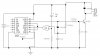
I have a circuit here that looks like this:
**broken link removed**

my problem is, how could i apply a power on reset for this circuit because everytime I apply power on it the relay energizes. I have already used the other flipflop on the 4013 for other purposes. Thanks in advance! :) :)
 
Try removing the bottom terminal of the cap from GND and reconnecting it to +12V, i.e., across the 1Meg resistor.
 
Last edited:
I would move one end of 1N4148 to +12V instead of Q output and exchange physically the 1M resistor and capacitor.

So the capacitor ends up being connected between +12V and pin10, with a diode to discharge it should +12V is off. The 1M resistor from pin10 to 0V charges up the capacitor during power ON and releasing the reset on the latch a few moment later.
 
eblc1388 said:
I would move one end of 1N4148 to +12V instead of Q output and exchange physically the 1M resistor and capacitor.

So the capacitor ends up being connected between +12V and pin10, with a diode to discharge it should +12V is off. The 1M resistor from pin10 to 0V charges up the capacitor during power ON and releasing the reset on the latch a few moment later.
He's making a one-shot, i.e., a monostable multivibrator. Each time he triggers it on "+pulse in", he wants a short pulse at the Q2 output. The circuit he has drawn will do that. I don't think your idea will.
 
You're right Ron. I responded to the POR arrangement but missed the one-shot requirement.
 
Ron H said:
Try removing the bottom terminal of the cap from GND and reconnecting it to +12V, i.e., across the 1Meg resistor.
i did the modifications Ron mentioned but i think the flipflop is in reset state all the time...
Any more inputs? :confused: :confused: this is the only part of my circuit that is not working as expected... Thanks in advance.
 
You need some extra logic to drive pin 10 of the 4013 high on power up.
 

Attachments

  • ff.jpg
    ff.jpg
    27.8 KB · Views: 349
nok6600app said:
i did the modifications Ron mentioned but i think the flipflop is in reset state all the time...

It could be the one-shot delay is too short for you to notice.

Before trying Kchriste's suggestion, which is a proper one by the way, you may try to increase the 1M resistor to 10M and/or increase the value of capacitor to 10uF as the previous values give a very short timing period.
 
kchriste said:
You need some extra logic to drive pin 10 of the 4013 high on power up.

thanks for the idea man :) :) must implement that!

eblc1388 said:
you may try to increase the 1M resistor to 10M and/or increase the value of capacitor to 10uF as the previous values give a very short timing period
I tried different timing values already... none of them worked on my circuit.
Thanks for all the replies guys... really appreciate it!
 
nok6600app said:
i did the modifications Ron mentioned but i think the flipflop is in reset state all the time...
Any more inputs? :confused: :confused: this is the only part of my circuit that is not working as expected... Thanks in advance.
It worked in simulation. Post a schematic of the mod you made.
 
nok6600app:
the circuit schematic does not show the connection
to the circuit that is to generate the trigger signal on pin_11, CP2.

The 4013 is a CMOS device very high Input impedance.
If it is Left Open Circuit for tsting, pin_11 might couple turn-on transients to the CMOS that trigger the 4013.

Rule: Always connect unused digital circuit inputs to Gnd when not used. For testing use these inputs can be held down thru a 100k resistor.

hawk2eye
 
Status
Not open for further replies.

Latest threads

New Articles From Microcontroller Tips

Back
Top