Hank102938
New Member
I've come to the conclusion that a linear regulator isn't my best bet, or if it is, I must have missed the memo.
What if I asked you this, forget all the other stuff we've been over...
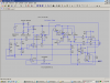
I have a 25VCT transformer and full wave rectifier. How can I build a variable power supply [close to] 0V to 24VDC at min. 1A output? With built in analog volt meter, oh, and throw in variable current limit with an analog ammeter too.
SURELY somewhere there is a design for something like that! I've spend at least 24 hours total trying to figure this thing out... And you know, I'm going to be pretty -insert choice words here- off if I don't end up with something that works. At this point I'm not too worried about what I have to spend (within reason) to make it work, I just want something I can say I made and that works. I'm counting on your help and reply, but please, excuse my anger, this:
What if I asked you this, forget all the other stuff we've been over...
I have a 25VCT transformer and full wave rectifier. How can I build a variable power supply [close to] 0V to 24VDC at min. 1A output? With built in analog volt meter, oh, and throw in variable current limit with an analog ammeter too.
SURELY somewhere there is a design for something like that! I've spend at least 24 hours total trying to figure this thing out... And you know, I'm going to be pretty -insert choice words here- off if I don't end up with something that works. At this point I'm not too worried about what I have to spend (within reason) to make it work, I just want something I can say I made and that works. I'm counting on your help and reply, but please, excuse my anger, this:
is not the reply I'm looking for. I know something, just not everything. If you've got any useful suggestions than please, let me know. Otherwise, I truly have appreciated everyone's help and good day to you... or night, or what ever time it is where you might be. Thanks.The calculation uses grade 4 simple arithmatic.
Last edited:
") But it looks like a lot of work.... of course the time spent trying to fix the old design is considerably more than what it would take to solder this thing up... I do have an cheap multi meter, but I don't think the ammeter part works. (either that or I don't know how to test current) or I could get the same meter for $10 or so. Just a few questions, can I still use my current transformer, can I use perfboard or will that just make it 100x harder and are you sure this is about as simple as its going to get for what I want? If you can price it out with out the meters that would be great, but don't waste your time on it, I'm just as capable of doing it...
But it looks like a lot of work.... of course the time spent trying to fix the old design is considerably more than what it would take to solder this thing up... I do have an cheap multi meter, but I don't think the ammeter part works. (either that or I don't know how to test current) or I could get the same meter for $10 or so. Just a few questions, can I still use my current transformer, can I use perfboard or will that just make it 100x harder and are you sure this is about as simple as its going to get for what I want? If you can price it out with out the meters that would be great, but don't waste your time on it, I'm just as capable of doing it...