Continue to Site

Welcome to our site!

Electro Tech is an online community (with over 170,000 members) who enjoy talking about and building electronic circuits, projects and gadgets. To participate you need to register. Registration is free. Click here to register now.

  • Welcome to our site! Electro Tech is an online community (with over 170,000 members) who enjoy talking about and building electronic circuits, projects and gadgets. To participate you need to register. Registration is free. Click here to register now.

power switching circuit isolation problem

Status
Not open for further replies.

reubenT

New Member
Is there anyone here who likes a switching circuit challenge? (although it may not be much of a challenge for an electronics engineer)

I've been trying to solve a little switching problem, simple as it should be I've only come up with a somewhat complex answer.
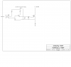
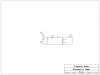
I have a 12V on/off signal source I need to use to switch high voltage up to several hundred V. The high voltage will be used to charge a film capacitor, and the charge power needs to be turned off during capacitor discharge, since it will be virtually short circuit discharge. The charge/discharge cycles will run about 15 per second up to as high as 25-30 for some applications.

Both power sources and the capacitor are on common ground.


I have HGTP10N120BN IGBT transistors for switching the power. FETbipolar 1200V 35 amp.

The problem I run into is that when the capacitor charges up, the transistor has a high voltage on it's emitter, which requires an isolated from ground voltage source applied to gate/emitter to hold it on, with the isolated power having it's negative side on the emitter which is the positive side of the charged capacitor. But the isolated/ungrounded voltage signal has to be turned on by the grounded signal, the high voltage can feed back into the signal source and destroy the components because the origin of the signal is common ground with the HV. therefor it looks like I need complete isolation between signal source and switch with an isolated (from ground) power supply running the inbetween circuitry. So how do I transfer the grounded signal source to an identical ungrounded signal? The only thing I can think of to completely isolate the grounded signal source from the HV on the emitter of the IGBT is an optocoupler.

I'm wondering if there's a better way. perhaps a diode in the right place? If not I will go ahead and order some optocouplers and try it.
 
Last edited:
Why not use a 12 V Power Oscillator driving a Step Up transformer and a Bridge rectifier to charge the capacitor?

Seems the simplest to me unless there are other unmentioned factors.

Ramesh
 
Take a look at IRFs PVI line of photo voltaic devices.

They are opto couplers that generate 5-10 volts on their output when you light up the LED. There not very fast and the output current is pretty small, but they should do fine in your case to drive a mosfet in your application.

**broken link removed**
 
The problem I run into is that when the capacitor charges up, the transistor has a high voltage on it's emitter, which requires an isolated from ground voltage source applied to gate/emitter to hold it on, with the isolated power having it's negative side on the emitter which is the positive side of the charged capacitor.
Can you post a schematic of your present set-up?
 
I have Express SCH program and drew a schematic, but can't figure out how to transfer it. (it may be simple but I didn't grow up with computers) But anyway, I saved that application notes booklet since it is addressing what I'm dealing with.
Looks like the photovoltiac isolater would eliminate a voltage amplifier stage. but the cost is a bit higher than a standard photo coupler with 3 resisters and a small transistor.
I'm trying to simplify it as much as possible, but I can't get it to work (on paper) without a drive signal isolator of some kind and a non grounded power supply, so I guess that's what will have to be done.
 
can't figure out how to transfer it.
Click the 'Go Advanced' button at the foot of this page, then scroll down the new page and click 'Manage Attachments' then 'Browse' then choose the file then 'Upload'.
 
One crazy thing is; on the Express SCH program it has a "copy diagram to clipboard" command, I do that but then I don't know where to find the "clipboard"

I saved it in a different manner and am trying it. It's the simplest circuit I can think up that might do the job.
 

Attachments

  • Circuit diagram.sch
    5.4 KB · Views: 181
You can then paste it into anything. I used paint. Then save it as a .png file and everyone can see it not just those with express.
 

Attachments

  • opto.png
    opto.png
    41 KB · Views: 233
Hmm. No Takers. :p

Lets try this. The one you have has trouble turning off the FET.
 

Attachments

  • HV Switch.png
    HV Switch.png
    147.3 KB · Views: 227
Post deleted.
 
Ok, thanks ronv. I need to understand it's operation; I see where Q1 turns on M1 and Q2 turns it off, (instead of the resister I am using to drain the capacitive charge off the gate, I suppose that would turn it off quicker) But why put two zeners cathode to cathode instead of one? The purpose of one 15V zener is to insure that no voltage spike ever exceeds 20V on the gate. It seems like two connected like that cancel each other and do nothing. (unless it does something not obvious)

And what is the purpose of M2? It is placed across the full voltage of the charged capacitor with no resistance, which would burn it out if it were on any time except when capacitor was discharged. Since the charged capacitor will be somewhat large, a high grade pulse duty film capacitor, may need some small resistance to limit charge current within transistor capability, or more than 1 transistor in parallel if it ends up being too much for one to handle.
In my application the switch is kept on for maybe 80% of a cycle, turned off momentarily, (a mechanical switch in preliminary experiments, but hall effect switching will be the main method) the charged capacitor discharges catastrophically through a HV diode into an arc fired by a coil, then the switch turns back on to recharge capacitor. The only reason to turn off the charge to the capacitor is to prevent the supply power from shorting out along with the discharging capacitor.


I put it together with a pair of LED's for an optocoupler, but didn't get enough voltage to turn on the 2N3904 NPN, (the LED produced .35V dropping to .1V under load) will try it with an optointerrupter with photo transistor output next. Just trying it with what I have since I don't have an optocoupler. Once I get it working I will do a simulated test with a dual channel oscilloscope to be sure the charge is off when the HV coil fires.
 
I don't know how fast the discharge takes place but I suspect really fast. I used M2 to simulate your discharge (Just for the simulation). When the cap discharges the source is pulled negative with respect to the gate. Since the is capacitance and some leakage on the gate the FET turns on again. This caused a big current spike thru M1. With the transistor the gate to source are tightly coupled. I'm not sure how your IBGT will act. I'll look around for a model.
The zener looks like a diode in one direction and a zener in the other so this configuration protects the gate to source in both directions but still allows the FET to turn on. I'm not sure they are needed but with 500 volts and a few amps flying around I thought you were wise to put them in.
 
I ran it with an IGBT to compare. Looks better with the IGBT (lower gate capacitance I suspect). There a quite a few unknowns.
How fast is the discharge.
Limiting resistance etc.
Size of capacitor.

Anyway, you can see the effect.
 

Attachments

  • disc..png
    disc..png
    240.3 KB · Views: 236
Ah; thanks; My electronic thinking is a bit slow and/or rusty. After all it's been almost 30 years since I was studying it, and that was entirely radio circuits, haven't done much since, other than put together a few variable pulsewidth motor control circuits.

OK so it really needs an active gate discharge to take the gate down to 0 with the source, (or emitter in the case of the IGBT) and keep it there. I have a bunch of 2N3906 that should work, although a bit lower current capacity than the 2N2907.

The actual circuit function I need right now is fairly fast turn off, but delay in turn on. Since the control signal is turning on the same instant the capacitor is discharged, and I need the IGBT turning on after it's finished discharging. (The next version will be hall IC switched and have the delay built into the timing circuit) So I'm thinking of putting a resister on the NPN, either collector or emitter side, a small capacitor grounded to IGBT emmiter, and then a small resistor to prevent overloading the PNP in discharge. But that will cause a gradual rise in voltage on the IGBT gate as the capacitor charges. (May not be good for the IGBT) A zener would prevent the gate from getting charge V until it exceeds zener threshold, giving some delay and faster rise time. I put 10V zener on the diagram but 12 might be better with a 14V supply, since the HGTP10N120BN IGBT needs in excess of 12 V to fully turn on.

The main film capacitor will be changeable until I find out how much is needed, I have several 20, 40, and 60 uF motor run capacitors to work with.

The purpose is to develop a circuit that will duplicate the function of a manufactured unit called "blue phoenix ignition" but to be a lot hotter than it, since we've tried the blue phoenix and it's not hot enough to do what we want, (what is supposed to be possible) and the size of it tells me they aren't using a vary big capacitor.
 

Attachments

  • delay switch diagram.PNG
    delay switch diagram.PNG
    57.6 KB · Views: 258
Hmmm. Not sure I know how this works. I'm assuming the plan is to add current to the high voltage to the spark plug? If so it seems like the cap would short out the 30,000 volts not add to it.
If you only need 30 cps I'm not sure you need an IGBT. A few amps would charge up the cap to 500 volts in 25 msec. But where will you get the 500 volt supply at a few amps? Anyway I would put the delay before the opto. I don't think you want the transistor turning on slowly. Might need a logic gate and another transistor, but it would be sharper.
Maybe there is someone here that has some experience with these things. I smell snake oil, so I'm probably not the best to help.:D
 
well; I'm experimenting, It will discharge through a HV diode to block backfeed, A spark jumping a gap creates a low resistance path and then the cap shorts out through the path creating a plasma arc. the IGBT devices are cheap enough, had a bunch from a previous project. If I blow a few components in the process no serious harm done. The manufactured version called "blue phoenix" obtains some interesting results with only 50 watts, but I have reason to think even better results can be had with a stronger system. I have the timing circuit ready to test but had to spend time on other stuff, like replacing wheel bearings in my dad's car, and an axle in my jeep. Soon as i can get to it I'll put a variable pulsewidth square wave generator on it for testing to simulate operating condition and watch both sides at once with the oscilloscope. I've seen it working with a manual switch, I just need to make it work with an electronic switch.
 
test was successful, circuit works including the delay function at 27 Hz which is as low as my pulse board will run at, and about maximum speed it would run in operation. but it looks like the 10-12V zener is not needed, since the IGBT does not turn on until voltage on the gate exceeds zener voltage anyway. (tiny little shelf on the gate voltage rise at zener voltage threshold as it charges IGBT gate capacitance, but it didn't show up in the IGBT output voltage with a small load on it) So with 2K and a 3-4 uF cap. to charge the gate I'm getting suitable delay, (will try raising resistance and lowering capacitance so I can use a common film cap instead of the electro) and a 22 resistor on the discharge gives plenty fast turnoff. (might be fine without anything but I didn't want to over-surge the PNP) next test will be to set it up in operating situation and see what happens.
 
Status
Not open for further replies.

Latest threads

New Articles From Microcontroller Tips

Back
Top