So,,,
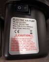
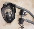
I have decided that I need a powered respirator for varnishing (moisture cured polyurethane contains isocyanate, not a good smell). I made one using a full face snorkeling mask and air blower (thanks Youtube) tested it using a bench power supply and it works great (so far, so good).
Now I want to make it portable:
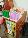
I have a good supply of tested 18650's that while not new, are good enough for this job (as per photo). I want to make 3 power packs using a 4s3p battery layout (I have a home made spot welder to make the packs up). I could also go to a 5s3p layout, but would prefer not to.
I was intending to use the following:
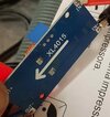
- BMS (1 per pack): 4s BMS
- Option to charge via USB (only need one): 4s USB charger
- Battery level indicator (really only NEED one, but I might put 1 per pack): Power level indicator
- I already have a DC-DC buck converter to get the required 12v DC-DC buck converter
- And finally a motor speed controller (PWM I assume): PWM speed control
During testing I found running the pump @ 12v it was too powerful, so need to reduce the airflow (hence = speed controller)
I realise that I can use the DC-DC converter to reduce the voltage, but the adjusting screw is REALLY small, and I want to use an easy-to-get-at control, plus there is a risk that I might go above the rated 12v to the motor, so just use the buck converter to set a regulated voltage (12v) and use a motor controller after that.
My Question(s):
If I am going to use the above speed controller do I even need the DC-DC converter, and will there be any 'interference' using a PWM motor controller 'Downstream' of the buck converter?
The preferred BMS has a discharge cut-out at 2.55v - what if I wanted to set the cut-out at 3.25v (14v for the pack), how could I do that?
I know these are basic questions (and yes I am totally noob) - but that should mean they are easy for you knowledgeable people to answer (I hope).
I have attached some pictures to assist with 'context'
I have decided that I need a powered respirator for varnishing (moisture cured polyurethane contains isocyanate, not a good smell). I made one using a full face snorkeling mask and air blower (thanks Youtube) tested it using a bench power supply and it works great (so far, so good).
Now I want to make it portable:
I have a good supply of tested 18650's that while not new, are good enough for this job (as per photo). I want to make 3 power packs using a 4s3p battery layout (I have a home made spot welder to make the packs up). I could also go to a 5s3p layout, but would prefer not to.
I was intending to use the following:
- BMS (1 per pack): 4s BMS
- Option to charge via USB (only need one): 4s USB charger
- Battery level indicator (really only NEED one, but I might put 1 per pack): Power level indicator
- I already have a DC-DC buck converter to get the required 12v DC-DC buck converter
- And finally a motor speed controller (PWM I assume): PWM speed control
During testing I found running the pump @ 12v it was too powerful, so need to reduce the airflow (hence = speed controller)
I realise that I can use the DC-DC converter to reduce the voltage, but the adjusting screw is REALLY small, and I want to use an easy-to-get-at control, plus there is a risk that I might go above the rated 12v to the motor, so just use the buck converter to set a regulated voltage (12v) and use a motor controller after that.
My Question(s):
If I am going to use the above speed controller do I even need the DC-DC converter, and will there be any 'interference' using a PWM motor controller 'Downstream' of the buck converter?
The preferred BMS has a discharge cut-out at 2.55v - what if I wanted to set the cut-out at 3.25v (14v for the pack), how could I do that?
I know these are basic questions (and yes I am totally noob) - but that should mean they are easy for you knowledgeable people to answer (I hope).
I have attached some pictures to assist with 'context'
")