Continue to Site

Welcome to our site!

Electro Tech is an online community (with over 170,000 members) who enjoy talking about and building electronic circuits, projects and gadgets. To participate you need to register. Registration is free. Click here to register now.

  • Welcome to our site! Electro Tech is an online community (with over 170,000 members) who enjoy talking about and building electronic circuits, projects and gadgets. To participate you need to register. Registration is free. Click here to register now.

Printer power control circuit

Status
Not open for further replies.

Torben

Well-Known Member
Hi all,

Still working on my automatic printer control circuit.

Background: I wanted to be able to print without having to have to go boot up the Mac which is in the same room as the printer. So I put a print spooler on a TS-7400 board I had around (running Debian Linux 4.0) and am using that as a network print server. It works great but I want to have the thing obey the following rules:

o If a print job is detected, turn on power to the printer.
o If no print job has been detected for x minutes (x being configurable) then turn the power to the printer off.

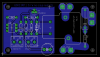
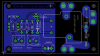
So far, I have breadboarded the control software and circuit to control the 9V relay from the TS-7400's 3.3V logic outputs, and that all works great. I just hope someone can give me some more eyeballs on my schematic and board layout.

I am especially unsure about the snubber across the load. I think the values are pretty OK from what I've read, but I have not yet performed any spark tests with the printer's power cord so I don't even know whether it's necessary.

Also I wonder if running the coil for longish periods of time every so often (maybe a few hours on at the extreme) will be bad for it. I could go to a latching relay if this won't last long under typical home use. We don't print every day, or even every week. ;)

schem_2-png.21717


board_2-png.21718


Other things which might be useful to know: it's a Lexmark E232 laser printer, with the markings "600W 6A" on the back. The relay I am using is an SPST rated for 15A at 125VAC; the coil is rated for 9VDC.


Any problems/corrections/ideas welcomed!


Thanks,

Torben
 

Attachments

  • schem_2.png
    schem_2.png
    6.5 KB · Views: 409
  • board_2.png
    board_2.png
    16 KB · Views: 518
I don't see the reason for R2 or R3. R4 maybe. Why such a monster size cap?
 
I don't see the reason for R2 or R3. R4 maybe. Why such a monster size cap?

R2 is there because I wanted to make sure that the base of the 3904 is held low when not forced high. Is the base floating better than pulled down like that, or just unnecessary?

R3 is there because I saw it on an example schematic. :) . . .just checked, and it works in the sim and on the breadboard just fine without R3. Thanks!

R4 is there to limit current to the coil. The wall warts I have on hand are rated at a min. 300mA so they show higher than 9VDC at this current level (the coil wants 93mA) and especially since the coil might be held high for long stretches of time (max. a few hours, more usually 30-45 minutes).

The monster cap is because I haven't yet scoped my wall warts and I'm assuming that there will be only half-wave rectifiers in them, and I want to keep coil ripple low. So I oversized the input cap. "Nuke the entire site from orbit. It's the only way to be sure". :)

Overkill?


Thanks,

Torben
 
OK, after sleeping for a few hours I looked at this again with a (hopefully) clearer head.

I've removed R2 and R3 from my test circuit and it works fine without them, so I'm happy about that. Thanks for mentioning those Mike--saves a little space (and a little current too).

Does anybody have any idea about the snubber? I understand that without being able to test the load properly it's hard to say for sure but I think the values given, using say a 2W carbon resistor and maybe a 600V poly cap, should be a good starting point.


Torben
 
I've removed R2 and R3 from my test circuit and it works fine without them, so I'm happy about that. Thanks for mentioning those Mike--saves a little space (and a little current too).

R3 was completely pointless, but R2 is good practice to fit - it may work most of the time, but if the driver transistor (in the opto-coupler) starts to leak very slightly, it will turn the transistor partially ON - R2 prevents this.

Any current saving is miniscule (70uA?).
 
R3 was completely pointless, but R2 is good practice to fit - it may work most of the time, but if the driver transistor (in the opto-coupler) starts to leak very slightly, it will turn the transistor partially ON - R2 prevents this.

Any current saving is miniscule (70uA?).

OK, that's why I originally had R2 in there. Back into the circuit it goes, then. I wasn't really worried about the current wasted since it's so tiny, especially when you put it next to the laser printer load. The LEDs on the printer use more juice.

Thanks for the explanation and confirmation.


Torben
 
Hm. I briefly checked the printer for arcing using the simple test of slowly plugging it in and and unplugging it while it was turned on (there is a mechanical switch in the back) and watching carefully to see if I could see or hear (or smell) any arcing. I was rather surprised to not notice any arcing at all. I had thought there would have been some.

However, the printer was not actually printing at the time so the motor was not running. I intend to test that tomorrow.

I was expecting at least some arcing, given the motor and fuser. Do modern laser printer power supplies often include back EMF protection? I would think it's anything but a resistive load.

Also, I scoped the two 9VDC 300mA wall warts I have and both are much more nicely behaved than I thought they would be. I will probably use a smaller input cap (I'm thinking 470uF) but leave 2200uF marked just in case.

Here are the updated schematic and board:

schem_4-png.21748


board_4-png.21749


I think the traces on the 120VAC side should be OK for what I want to do but I am planning to solder down 16 AVG solid core along those traces anyway just to be sure. Is that overkill?


Torben
 

Attachments

  • schem_4.png
    schem_4.png
    6.7 KB · Views: 380
  • board_4.png
    board_4.png
    13.3 KB · Views: 436
Last edited:
Howcome you lowered R3 to 1K? You are cutting your base drive in half. I would say the 10k was better.
 
Last edited:
Howcome you lowered R3 to 1K? You are cutting your base drive in half. I would say the 10k was better.

erm. . .because that was a typo when I updated the schematic. :) It's still 10k in the test circuit. Oops.

[Edit: Fixed in the schematic and board images.]


Torben
 
Last edited:
OK, I figured out why my wall warts are so well-behaved, the hard way. I smoked one so I dissected it and found a nice full-wave bridge comprising four 1N4004 diodes, a fairly big transformer, and a 2200uF cap. The transformer appears to be the part which died. The problem was a direct short on the wall wart output.

Another wall-wart I have performs similarly so I will use that and I feel I can now bring the cap value down to 100uF.


Torben
 
Status
Not open for further replies.

Latest threads

New Articles From Microcontroller Tips

Back
Top