Continue to Site

Welcome to our site!

Electro Tech is an online community (with over 170,000 members) who enjoy talking about and building electronic circuits, projects and gadgets. To participate you need to register. Registration is free. Click here to register now.

  • Welcome to our site! Electro Tech is an online community (with over 170,000 members) who enjoy talking about and building electronic circuits, projects and gadgets. To participate you need to register. Registration is free. Click here to register now.

Question about connecting digispark pin P1 to led driver board with PWM pin...

Status
Not open for further replies.
Mike,
I believe my LED driver board was bricked. I had tried so many different connections today that I zapped it at some point apparently, probably last night. I found this out after my led burned out after being on for approx 15 seconds. I had 12v going straight through the driver board. Now, with a new board and the LED pin 1 from the digispark connected to the PWM pin on the board, my fade sequence is working, although backwards as I have not uploaded my inverted sketch yet.
I did notice that the fading did not seem as 'smooth' as it normally does. I assume this is due to the 500 Hz from the digispark and the 200Hz (+/-) expected by the driver board. Does that make sense? If so, how do I incorporate the Hz frequency code into my sketch? Your modified code has been added to the end of my sketch below: THANK YOU


Code:
   /*
 VISIBLE_FEEDER_LIGHT_SKETCH_700ma

  The circuit:
 * LED (+) attached to PWM pin 1.
 * motion sensor 'signal' attached to pin 2 
 * digispark microcontroller

 last edit 8/17/2017
 By John A. Austin


 */
int sensorPin = 2;  //motion sensor out pin connected to digital pin 2 (P2 on digispark) 
int ledPin = 1;    // LED connected to digital pin 1 (P1 on digispark) 
int fadeValue = 255; //initial led brightness (variable)
//int analogValue = analogRead(ledPin);

void setup()
{
// initialize the sensorPin as an input:
  pinMode(sensorPin, INPUT);
// initialize the ledPin as an output:
  pinMode(ledPin, OUTPUT);
}

//FUNCTIONALITY is reverse logic based on LED driver board PWM pin:
//read status of motion sensor (HIGH or LOW)
//If HIGH, fade leds from off to on over a one minute period
//then fade to off over a 32 second period
//wait 5 seconds and read sensor pin again


void loop()
{
  analogWrite(ledPin, 255);
  delay(5000);
if(digitalRead(sensorPin) == LOW) //if no signal is sent to P2 from sensor, it will loop back to start, then delay 5 seconds and read again:
{
  loop;
}
  else
{
for (int fadeValue = 255 ; fadeValue >= 0; fadeValue -= 1)
{
 analogWrite(ledPin, fadeValue); 
 delay(235);
}    
{
 analogWrite(ledPin, 0);
 delay(300000);
}
{
for (int fadeValue = 0 ; fadeValue <= 255 ; fadeValue += 1)
{  
 analogWrite(ledPin, fadeValue);
 delay(125);
}
}
}
}
}
//loop while ...
//digitalWrite(ledPin,1);
//delayMicroseconds (4750); //95% duty cycle at 200Mz - delay 1
//digitalWrite(ledPin,0);
//delayMicroseconds(250); //delay 2
//end loop

//where 0<x<5000
 
Yes, and the 100Hz problem is as simple as :

pin=some pin; //a contant.
Per=1e6/PwmFreq; //a constant.
x=3900; //a variable related to duty cycle such that 0<x<Per

Loop while ... //some kind of loop...
digitalwrite(pin,high);
delaymicroseconds (x);
digitalwrite(pin,low);
delaymicroseconds(Per-x);​
end loop;

Mike,

I think I was confused.....
This is the actual fade sequence above, isn't it? Of course I will need to tweak it to meet my specific requirements and designations, like pin names, etc...
The longer duration specified for the digital HIGH along with the shorter duration of the digital LOW, determines the brightness, right? Doing away with my analogWrite functions altogether?
And, since the total duration of HIGH and LOW combines to equal 5ms, I am sending a PWM at 200 Hz? Basically, I will be replacing and simplifying my fade sequence altogether and not incorporating your code into my sketch, correct?
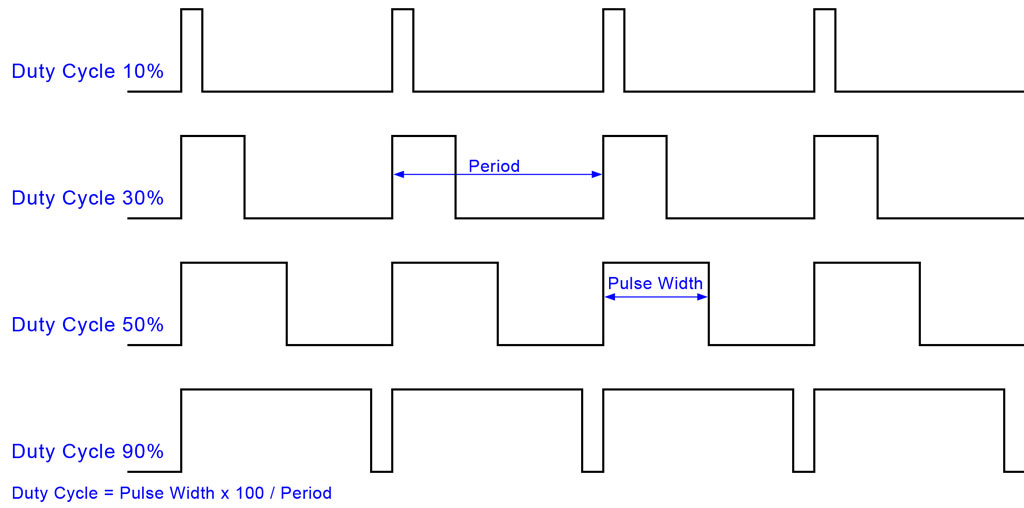
The PWM patterns below would represent a dim led at 10% and a bright led at 90%, but each period being 5ms or 200Hz? As my sketch loops, it would add or subtract the delay value to/from 'period' and brighten or dim the leds.... Do I understand this correctly now? Of course, with my led driver being reverse logic, I will need to add time to the HIGH delay duration to reduce the brightness of my leds, right?

atmega168a_pwm_02.jpg
 
Actually still confused..... I need my leds to fade on slowly over a 60 second time period, hold at HIGH for 5 minutes, then slowly fade down. I probably need to keep my sketch but need to figure out how to accommodate the 200Hz.. :banghead:
 
You might find this video helpful, seems it is the same chip as your board.

Though it looks at the PWM pins only so far as showing how to switch off the led; it does not mention the pwm frequency.

Not seen any mention of using these boards with PWM and nothing in the Arduino arena, which make me suspicious.

Now you can see / have it wired correctly, have you tried a simple sketch using the C++ AnalogueWrite at 500hz to see if it does run with that frequency ? eg the /Examples/ Analogue/ Fading sketch from the Arduino ide
 
Actually still confused..... I need my leds to fade on slowly over a 60 second time period, hold at HIGH for 5 minutes, then slowly fade down. I probably need to keep my sketch but need to figure out how to accommodate the 200Hz.. :banghead:

Yes, make the code snippet I posted a local function which will replace AnalogWrite(). Say we call it PWM(). In addition to pin and value, it will need a third argument passed to it which is how long (duration, based on time) to do the PWM loop before returning to the calling code.

To do the slow fade over 60 seconds, call the new PWM(pin,value,duration) function 60 times, each time the pin=constant and duration=1s, but value will change second by second.

To do the 5min constant on, I would just set the pin high and use a variant of this to do the timing.
 
You might find this video helpful, seems it is the same chip as your board.

Though it looks at the PWM pins only so far as showing how to switch off the led; it does not mention the pwm frequency.

Not seen any mention of using these boards with PWM and nothing in the Arduino arena, which make me suspicious.

Now you can see / have it wired correctly, have you tried a simple sketch using the C++ AnalogueWrite at 500hz to see if it does run with that frequency ? eg the /Examples/ Analogue/ Fading sketch from the Arduino ide
I ran across that video several days ago. The problem is he simply indicates that the board will handle PWM by attaching a AA battery and nothing further.
 
Yes, make the code snippet I posted a local function which will replace AnalogWrite(). Say we call it PWM(). In addition to pin and value, it will need a third argument passed to it which is how long (duration, based on time) to do the PWM loop before returning to the calling code.

To do the slow fade over 60 seconds, call the new PWM(pin,value,duration) function 60 times, each time the pin=constant and duration=1s, but value will change second by second.

To do the 5min constant on, I would just set the pin high and use a variant of this to do the timing.

Ok, Great! I will get my sketch modified today/tonight and test it on the breadboard. Thank you for the link to 'local function'. It looks very straight forward. And thanks for the specific instruction. This helps me tremendously and this info should get me there. :happy:
 
In addition to pin and value, it will need a third argument passed to it which is how long (duration, based on time) to do the PWM loop before returning to the calling code.

To do the slow fade over 60 seconds, call the new PWM(pin,value,duration) function 60 times, each time the pin=constant and duration=1s, but value will change second by second.
Mike,
My sketch, as progressed so far, is below. It does compile. However, I am just not clear about adding the third argument which would regulate the duration. I am also not clear as to how I go about 'calling' my function 60 times. Actually, I plan to call the function 180 times as the duration will only be 1/3 second. I have done some searching, but am not finding an example for calling a function multiple times. With your help, I should have this light functioning properly soon. Maybe I can test it tonight. Thanks again...

Code:
   /*
 VISIBLE_FEEDER_LIGHT_SKETCH_700ma

  The circuit:
 * motion sensor 'signal' will be attached to pin 2 
 * digispark microcontroller
 * digispark's Pin 1 is connected to the PWM pin on the XL4001 led driver module (reverse logic)

 last edit 8/17/2017
 By John A. Austin


 */
int sensorPin = 2;  //motion sensor out pin connected to digital pin 2 (P2 on digispark) 
int ledPin = 1;    // LED connected to digital pin 1 (P1 on digispark) 
int delay1 = 0; //HIGH pulse
int delay2 = 0; //LOW pulse
const int delayValue = 20;


void setup()
{
// initialize the sensorPin as an input:
  pinMode(sensorPin, INPUT);
// initialize the ledPin as an output:
  pinMode(ledPin, OUTPUT);
}
void PWM_UP() //to be called 180 times
{
while(0<delay1>5000);
digitalWrite(ledPin,1);
delayMicroseconds(delay1); //increase duty cycle at 200Hz - delay #1 - HIGH
digitalWrite(ledPin,0);
delayMicroseconds(delay2); //delay #2 - LOW
delay1 = delay1+delayValue;
delay2 = delay2-delayValue;
}
void PWM_DN() //to be called 180 times
{
while(0<delay1>5000);
digitalWrite(ledPin,0);
delayMicroseconds(delay1); //increase duty cycle at 200Hz - delay #1 - HIGH
digitalWrite(ledPin,0);
delayMicroseconds(delay2); //delay #2 - LOW
delay1 = delay1-delayValue;
delay2 = delay2+delayValue;
}

//FUNCTIONALITY: (REVERSE LOGIC FOR PWM ON DRIVER MODULE)
//read status of motion sensor (HIGH or LOW)
//If HIGH, fade leds from off to on over a one minute period
//then fade to off over a 32 second period
//wait 5 seconds and read sensor pin again

//IMPORTANT NOTE: reverse logic is required based on LED driver board's PWM pin functionality


void loop()
{
 analogWrite(ledPin,255);
 delay(5000);
if(digitalRead(sensorPin) == LOW) //if no signal is sent to P2 from motion sensor, then loop:
{
loop;
}
else
{
PWM_DN();
}
{
analogWrite(ledPin, 0); //remember reverse logic is required
delay(300000); //hold LED at full brightness for 5 minutes
}
PWM_UP();
}
 
The simplest way of doing anything 180 times is the For statement.

The index variable used by the For statement can be the PWM duty cycle argument directly.
 
GO TO POST #32

I have these two functions in my 'setup':

Code:
void PWM_UP() //to be called 60 times
{
while(0<delay1>5000);
digitalWrite(ledPin,HIGH);
delayMicroseconds(delay1); //increase duty cycle at 200Hz - delay #1 - HIGH
digitalWrite(ledPin,LOW);
delayMicroseconds(delay2); //delay #2 - LOW
delay1=delay1+delayValue;
delay2=5000-delay1;

}
void PWM_DN() //to be called 180 times
{
while(0<delay1>5000);
digitalWrite(ledPin,HIGH);
delayMicroseconds(delay1); //increase duty cycle at 200Hz - delay #1 - HIGH
digitalWrite(ledPin,LOW);
delayMicroseconds(delay2); //delay #2 - LOW
delay1=5000-delayValue;
delay2=delay2+delay1;
}

This is my main code:

Code:
void loop()
{
 analogWrite(ledPin,255);
 delay(5000);
if(digitalRead(sensorPin) == LOW) //if no signal is sent to P2 from motion sensor, then loop:
{
loop;
}
else
{
for (int i=0; i <= 180; i++)
{
PWM_DN();
}
{
analogWrite(ledPin, 255); //remember reverse logic is required
delay(10000); //hold LED at full brightness for 10 seconds for testing
}
for (i=0; i <= 60; i++)
{
PWM_UP();
}
[QUOTE="MikeMl, post: 1303091, member: 125427"]The index variable used by the For statement can be the PWM duty cycle argument directly.[/QUOTE]

}
}

I can tell that the sketch is trying to work, but I still do not understand how to accomplish the following. I'm not sure why I am not able to figure this out as your instructions seem quite clear and adequate... My setup and main code are shown above.... I am calling the functions properly I believe.
The duty cycle requires two time periods so how does the variable for the loop count figure into it? Also, I tried to add the 'PWM(pin,value,duration)' line and got a message that there were too many arguments.... and, where should this PWM(pin,value,duration) line be placed?


To do the slow fade over 60 seconds, call the new PWM(pin,value,duration) function 60 times, each time the pin=constant and duration=1s, but value will change second by second.

The index variable used by the For statement can be the PWM duty cycle argument directly.
 
Last edited:
Hi Mike,

I worked late trying to get my sketch to work. I finally changed the 200Hz period to 100Hz and my sketch appears to have the proper frequency now. However, the sketch starts with a very faint LED as expected, but seems to get caught in an endless loop at that point as the faint led remains until I remove power from the breadboard. So now, I have three issues to solve:
  • fix the endless loop so the sketch can continue
  • figure out specifically how and where to add the time delay for each loop to make the PWM_UP sequence last 60 seconds and vice versa
  • Try to figure out why I am now getting the error message shown below as there should be no reason for it to suddenly show up:arghh:
The full sketch is pasted at the bottom of this post.

Error message: why???
upload_2017-8-18_23-53-57.png


Code:
   /*
 VISIBLE_FEEDER_LIGHT_SKETCH_700ma

  The circuit:
 * LED (+) attached to pin 1.
 * motion sensor 'signal' will be attached to pin 2 
 * digispark microcontroller

 last edit 8/17/2017
 By John A. Austin


 */
int sensorPin = 2;  //motion sensor out pin connected to digital pin 2 (P2 on digispark) 
int ledPin = 1;    // LED driver module's PWM pin is connected to digital pin 1 (P1 on digispark) 
int delay1 = 9999; //HIGH pulse
int delay2 = 0; //LOW pulse
const int delayValue = 20;
int i = 1;
int ledLvl=1;


void setup()
{
// initialize the sensorPin as an input:
  pinMode(sensorPin, INPUT);
// initialize the ledPin as an output:
  pinMode(ledPin, OUTPUT);
}
void PWM_UP() //to be called 500 times

{
while(0<delay1>10000) {
digitalWrite(ledPin,LOW);
delayMicroseconds(delay1); //decrease duty cycle at 100Hz - delay #1 - LOW
digitalWrite(ledPin,HIGH);
delayMicroseconds(delay2); //delay #2 - HIGH
delay1=delay1-delayValue;
delay2=delay2+delayValue;
}
void PWM_DN() //to be called 500 times

{
while(0<delay1>10000) {
digitalWrite(ledPin,HIGH);
delayMicroseconds(delay1); //increase duty cycle at 100Hz - delay #1 - HIGH
digitalWrite(ledPin,LOW);
delayMicroseconds(delay2); //delay #2 - LOW
delay1=delay1-delayValue;
delay2=delay2+delayValue;
}

//FUNCTIONALITY: (WILL CHANGE TO REVERSE LOGIC FOR PWM ON DRIVER MODULE)
//read status of motion sensor (HIGH or LOW)
//If HIGH, fade leds from off to on over a one minute period
//then fade to off over a 32 second period
//wait 5 seconds and read sensor pin again

//IMPORTANT NOTE: reverse logic is required based on LED driver board's PWM pin functionality
//REVERSE LOGIC - CHANGE AFTER TESTING


void loop()
{
 analogWrite(ledPin,0);
 delay(5000);
if(digitalRead(sensorPin) == LOW) //if no signal is sent to P2 from motion sensor, then loop:
{
loop;
}
else
{
for (int i=0; i <= 500; i++)
{
PWM_UP();
ledLvl=analogRead(ledPin);
}
{
analogWrite(ledPin, ledLvl);
delay(10000);
}
{
for (i=0; i <= 500; i++)
{
PWM_DN();
ledLvl=analogRead(ledPin);
}
analogWrite(ledPin, ledLvl);
delay(10000);
}
}
}
}
}
}
 
Last edited:
I had a rogue '}' in my function that may have been causing the 'function not allow before...' error, but now I am getting this initializer error that I have not been getting during hours of testing this sketch:
upload_2017-8-19_10-36-52.png
 
Mike,
I finally have the sketch working properly I believe. The only thing I need to add are the delays to the PWM_UP & DN functions to slow things down.
I am currently getting what appears to be approx 7 blinks per second on the led. I am confident the led is fading up, then down very rapidly.
I have the 'for' statements placed in the functions themselves and commented out at this point. I'm not sure if they even go there. I then need to add the delay code(s) to regulate the up and down sequence. Can you help me with that?
Here is the code as it is now:
Code:
   /*
 VISIBLE_FEEDER_LIGHT_SKETCH_700ma

  The circuit:
 * LED (+) attached to pin 1.
 * motion sensor 'signal' will be attached to pin 2 
 * digispark microcontroller

 last edit 8/17/2017
 By John A. Austin


 */
int sensorPin = 2;  //motion sensor out pin connected to digital pin 2 (P2 on digispark) 
int ledPin = 1;    // LED driver module's PWM pin is connected to digital pin 1 (P1 on digispark) 
int delay1 = 9999; //HIGH pulse
int delay2 = 0; //LOW pulse
const int delayValue = 20;
int i = 1;
int ledLvl=1;


void setup()
{
// initialize the sensorPin as an input:
  pinMode(sensorPin, INPUT);
// initialize the ledPin as an output:
  pinMode(ledPin, OUTPUT);
}
void PWM_UP()
{
//for (int i=0; i <= 180; i++) //need to add .333 sec delay somewhere for a 1 min overall fade up duration
while(0<delay1>10000) 
digitalWrite(ledPin,LOW);
delayMicroseconds(delay1); //decrease duty cycle at 100Hz - delay #1 - LOW
digitalWrite(ledPin,HIGH);
delayMicroseconds(delay2); //delay #2 - HIGH
delay1=delay1-delayValue;
delay2=delay2+delayValue;
}
void PWM_DN()
{
//for (int i=0; i <= 60; i++) //need to add .333 sec delay somewhere for a 20 sec overall fade down duration
while(0<delay1>10000)
digitalWrite(ledPin,HIGH);
delayMicroseconds(delay1); //increase duty cycle at 100Hz - delay #1 - HIGH
digitalWrite(ledPin,LOW);
delayMicroseconds(delay2); //delay #2 - LOW
delay1=delay1-delayValue;
delay2=delay2+delayValue;
}

//FUNCTIONALITY: (WILL CHANGE TO REVERSE LOGIC FOR PWM ON DRIVER MODULE)
//read status of motion sensor (HIGH or LOW)
//If HIGH, fade leds from off to on over a one minute period
//Hold leds at 100% brightness for 5 minutes // this delay needs to be added back in 
//then fade to off over a 20 second period
//wait 5 seconds and read sensor pin again //this delay needs to be added back in

//IMPORTANT NOTE: reverse logic is required based on LED driver board's PWM pin functionality
//REVERSE LOGIC - CHANGE AFTER TESTING


void loop()
{
if(digitalRead(sensorPin) == LOW) //if no signal is sent to P2 from motion sensor, then loop:
{
loop;
}
else
{
{
PWM_UP();
}
//analogWrite(ledPin, 255); //set leds at full brightness
//delay(300000); //hold at full brightness for 5 minutes
{
PWM_DN();
}
//delay(5000);
}
}
 
You need braces after while statement.
I don't know if the compiler accepts the while statement as it is now.
Probably the statements in pwm_up and pwm_dn are executed only once

Should be something like this:
---------------
void PWM_UP()
{
//for (int i=0; i <= 60; i++) //need to add .333 sec delay somewhere for a 20 sec overall fade down duration

while( delay1 > 0 && delay1< 10000)
{
digitalWrite(ledPin,HIGH);
delayMicroseconds(delay1); //increase duty cycle at 100Hz - delay #1 - HIGH
digitalWrite(ledPin,LOW);
delayMicroseconds(delay2); //delay #2 - LOW
delay1=delay1-delayValue;
delay2=delay2+delayValue;
}
}

Same for PWM_DN()
 
I rearranged my sketch somewhat to make the PWM_UP/DN functions 'local', replacing my original analogWrite statements. I have a place holder at mid point for the 'PWM' to control the fading time(s) somehow????. This is as far as I can get:

You had stated
The index variable used by the For statement can be the PWM duty cycle argument directly.
,but isn't the 'duty cycle' a specific analog value from the digispark at a 500Hz frequency?? This is the main reason I am confused. In my mind, I have the two functions that adjust the pulse widths of the low/high in a fade up or fade down direction at 100Hz. So, I need to somehow have those functions loop at specific pulse width combinations (brightness levels) for 1/3 seconds before adjusting the pulse width to the next level, either brighter or dimmer.
All of this issue started because I was trying to control 3 high power leds requiring a current of 700ma and was frying my 2n3904 transistors. And mainly, the fact that my led driver PWM function only works at approx 100Hz and the digispark sends a pwm signal at 500Hz. Usually I can figure out a problem in a reasonable amount of time, but this is beating me.... At this point, I cannot logically envision the flow or function of your recommendations, and I have spent many, many hours trying. I do understand the PWM functions and the adjustments to the frequency in Hz. That is no big deal. But getting it to loop and hold at a specific graduation of pulse width has me stumped.


Code:
   /*
  The circuit:
 * LED (+) attached to pin 1.
 * motion sensor 'signal' will be attached to pin 2 
 * digispark microcontroller

 last edit 8/19/2017
 By John A. Austin


 */
int sensorPin = 2;  //motion sensor out pin connected to digital pin 2 (P2 on digispark) 
int ledPin = 1;    // LED driver module's PWM pin is connected to digital pin 1 (P1 on digispark) 
int delay1 = 9999; //HIGH pulse
int delay2 = 0; //LOW pulse
const int delayValue = 20;
int i = 1;
int ledLvl=1;
int x = 0;


void setup()
{
// initialize the sensorPin as an input:
  pinMode(sensorPin, INPUT);
// initialize the ledPin as an output:
  pinMode(ledPin, OUTPUT);
}


//FUNCTIONALITY: (WILL CHANGE TO REVERSE LOGIC FOR PWM ON DRIVER MODULE)
//read status of motion sensor (HIGH or LOW)
//If HIGH, fade leds from off to on over a one minute period
//then fade to off over a 32 second period
//wait 5 seconds and read sensor pin again

//IMPORTANT NOTE: reverse logic is required based on LED driver board's PWM pin functionality
//REVERSE LOGIC - CHANGE AFTER TESTING


void loop()
{
if(digitalRead(sensorPin) == LOW) //if no signal is sent to P2 from motion sensor, then loop:
{
loop;
}
else
{
void PWM_UP()

while(0<delay1>10000)
{
digitalWrite(ledPin,LOW);
delayMicroseconds(delay1);
digitalWrite(ledPin,HIGH);
delayMicroseconds(delay2);
delay1=delay1-delayValue;
delay2=delay2+delayValue;
PWM();
}
{
void PWM()
{
void PWM_DN()
while(0<delay1>10000)
{
digitalWrite(ledPin,HIGH);
delayMicroseconds(delay1);
digitalWrite(ledPin,LOW);
delayMicroseconds(delay2);
delay1=delay1-delayValue;
delay2=delay2+delayValue;
PWM();
}
}
//analogWrite(ledPin, 255); //set leds at full brightness
//delay(300000); //hold at full brightness for 5 minutes
}
}
}
 
Sorry, but I dont have the time to check your code right now, but if you want (say) 100 different steps of PWM duty cycle, each lasting the same duration, then if the index in the for loop runs from 0 to 99, the duty cycle % can also run 0% to 99%. The actual delay times (in us) would be computed from the index value (0 to 99) passed to the PWM sub by the loop...
 
Status
Not open for further replies.

Latest threads

New Articles From Microcontroller Tips

Back
Top