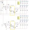
The formula above was used to peform the calculation for the upper section of the filter circuit but i would like to know how would the formula change if i needed to perform a similar calculation to the lower filter circuit. I have outlined both the upper and lower section of the Filter circuit.
Attachments
Last edited:
