Continue to Site

Welcome to our site!

Electro Tech is an online community (with over 170,000 members) who enjoy talking about and building electronic circuits, projects and gadgets. To participate you need to register. Registration is free. Click here to register now.

  • Welcome to our site! Electro Tech is an online community (with over 170,000 members) who enjoy talking about and building electronic circuits, projects and gadgets. To participate you need to register. Registration is free. Click here to register now.

Reduce 14v DC to 12v DC

adc1947

New Member
Hello.... first time posting... and need some help....

I need to reduce 14v dc to 12v dc.

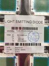
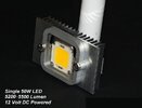
I have 48w LED that draws 4.5 amps at 12v. If powered at 14v, the amp draw increases to around 7 to 8 amps. LED is fine when powered with the 12v, but is greatly over heating at 14v.

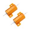
In searching internet for solution to reducing the 14v to 12v, I came across similar issue where there was a need to reduce 15v to 12v and the suggested solution was the use of a 0.6R 25w resistor.

Will the above work or should the 0.6R resistor be a different value since I am working with 14v and not 15v....??

I have found 0.6R resistors with 50w and 100w ratings, but have not purchased to try them.

Any help and comments will be much appreciated.
 
A couple of diodes with the appropriate ratings would be a better choice. Appropriate ratings is the key phrase here since 0.7V * 4.5 Amperes = 3.15 Watts. I would go with 5 watt diodes.
 
A couple of diodes with the appropriate ratings would be a better choice. Appropriate ratings is the key phrase here since 0.7V * 4.5 Amperes = 3.15 Watts. I would go with 5 watt diodes.
Appreciate the quick reply.... I know totally nothing about electronics and unfortunately, don't know how to utilize them :( .... Assume they would go in a series, in line on + side of DC... ?

The diodes need to be rated at 12v, right...? Such as these...?


...
 
Last edited:
There are several approaches;
  1. Constant Current limiter with the 1.5V drop or more limited by heat size, transistor to limit hotspot rise. More tolerant to input voltage changes.
  2. Constant voltage drop. As above assume input is constant.
  3. DC-DC Buck converter rated for 5A. Dimmable with adjustable voltage.
  4. Fixed power resistor 2V/4.5A=0.444 Ohms rated for more than 2V*4.5A=9W to reduce temp rise over 100 'C such as 15 to 25 W.
This one with heatsink tabs mounted on a metal heatsink run cooler. https://www.digikey.ca/en/products/detail/bourns-inc/PWR220T-20-R500F/2192695
0.5 Ohm being 12% higher might not be a significant drop in brightness from 0.444 but what if your 14V goes to 14.2V? Thats a 14% rise.
 
Appreciate the quick reply.... I know totally nothing about electronics and unfortunately, don't know how to utilize them :( .... Assume they would go in a series, in line on + side of DC... ?

The diodes need to be rated at 12v, right...? Such as these...?


...
I don't think you want a zener diode. An ordinary rectifier like a 1N4001-1n4007, depending on what is available. Each diode should drop between 0.6-0.8V depending on the current. Start with on diode and add one if required. They should be forward biased. That means the higher voltage should go on the anode and the lower voltage should go on the cathode.

If you really don't know WTF you are doing, might I suggest a series of low voltage, low current experiments with an adjustable power supply to characterize the devices.
 
This one with heatsink tabs mounted on a metal heatsink run cooler. https://www.digikey.ca/en/products/detail/bourns-inc/PWR220T-20-R500F/2192695
0.5 Ohm being 12% higher might not be a significant drop in brightness from 0.444 but what if your 14V goes to 14.2V? Thats a 14% rise.
I would like to use the one you link to above.... but, question first....
The LED is rated at 48w at 12v. The resistor specs shows to be 20w

PWR220T-20-R500F RESISTOR, THICK FILM PWR, 0.5 OHM, 20W

Not a problem...??

 
12V x 4.5A = 54 watts
You probably should be using a 4.5A constant current LED driver. Not a constant voltage power supply.
What is the part number for the LEDs?
The LED is designed to be used without a driver as long as voltage is 12v. Typical power is from 12v marine battery or sealed lead acid battery (8Ah). The problem has arisen when using a high amp automotive alternator that is putting out 14 volts to the battery that powers the light. When used with only 12v battery, no problems, but the 14v is destroying the LED.
 

Attachments

  • IMG_1543.JPG
    IMG_1543.JPG
    100.6 KB · Views: 52
Last edited:
Since a battery is not well voltage regulated, yet the LED current is specified with at least 3 significant figures, you better choose the constant current limited designs or DCDC Buck for <= 3850 mA and not 4500 mA at 12.x V. Since the LED is nonlinear yet equivalent to a linear 3.11 Ohms, the series 0.5 ohm 20W solution would change currents with the Alternator off but be the simplest "alternative. The dissipation power is proportion to the series resistance with shared current.
 
If you use either a power R or diodes in series to drop the nominal 2V, 4.5A, then you
have a power dissipation problem of 2 V x 4.5 A = 9W. So throw in some margin and use
components that are say 50% more than needed.

Also to protect LEDs against load dump in typical alternator based systems use a
transient suppressor to handle load dump :

1716231978419.png


Add that to your circuit, a MOV of appropriate ratings.

Regards, Dana.
 
These are the harsh voltages on wires shared by ACU clutches and starter solenoids due to wire inductance.; A battery with sufficient capacity would suppress the voltage (with low Rs) then send on separate wires to the LED not shared by inductive loads. Yet these are generic automotive standards for all cars.

I would choose a DCDC converter and adjust the voltage to 12 first then adjust the current to limit at or near <= 3.85 A for the present load but with the option to add more 12V LEDs.
 
The LED is designed to be used without a driver as long as voltage is 12v.
I disagree. I cannot find a data sheet, but I am certain it was no designed for a 12V power supply. It does have a Vf of 12V +/- some amount.
Looking a similar part. 12V=4.5A as tested by you. 15V=7.5A, from data sheet 9.5V=0A
You need a 4A constant current LED driver.
 
I disagree. I cannot find a data sheet, but I am certain it was no designed for a 12V power supply. It does have a Vf of 12V +/- some amount.
Looking a similar part. 12V=4.5A as tested by you. 15V=7.5A, from data sheet 9.5V=0A
You need a 4A constant current LED driver.
They do not require a driver... I have used this same LED as a marine boat light (photo below) without any issues as long as battery is 12volt. One boat has been in use for several years with out problems, however it is running a lesser output alternator (Delco one wire 65 amps). I do agree that a 4A constant current 12v LED driver would cure the problem

Here is same 12v LED currently sold on eBay:


Attachments

  • DSC_3975.JPG
    DSC_3975.JPG
    42.5 KB · Views: 46
They do not require a driver... I have used this same LED as a marine boat light (photo below) without any issues as long as battery is 12volt. One boat has been in use for several years with out problems, however it is running a lesser output alternator (Delco one wire 65 amps). I do agree that a 4A constant current 12v LED driver would cure the problem

Here is same 12v LED currently sold on eBay:

Those LEDs are supposed to be used with a driver. You may have got away with it on the boat, but at 4.5 A, you only need some long wires to limit the current like a resistor would do.

To drop 2 V at 4.5A needs 0.444 Ohms, but increasing the resistance will only dim the LED a bit. I would suggest somewhere between 0.5 and 1 Ohms, with one resistor per lamp. The resistor will get hot, so use 25 W resistors or larger, bolted to a heatsink.
 
They do not require a driver... I have used this same LED as a marine boat light (photo below) without any issues as long as battery is 12volt. One boat has been in use for several years with out problems, however it is running a lesser output alternator (Delco one wire 65 amps). I do agree that a 4A constant current 12v LED driver would cure the problem

Here is same 12v LED currently sold on eBay:

LEDs like all electronics have an MTBF reduction according to Arrhenius Law which is a thermal rise acceleration to failure rate. Thus to minimize the junction temperature rise above room temp., one must know the Thermal resistance and and the electrical series resistance to regulate the Tj to a cost-effective value of 85'C . This is easiest done with a current limiter or thermal limiter. Junction voltages reduce with a thermal rise of about -4mV/'C so a constant V or CV only makes sense with a continual ambient.

So a 3.85 A or LESS limiter is the optimal solution.
 
A linear design can only be 12V/14V *100% =85% efficient approx, not much different than a Buck regulator. so the series pass regulator transistor needs to pass at least 15% of the power of the load like a series resistor but regulated for current with feedback.. With a self-bias Rbc, the std. bipolar LDO drop of 0.7V to 1.5V can be reduced by a clever design change to < 0.2V. e.g. https://tinyurl.com/276p27ct. Here the 33 mohm current sense R dumps 0.5W should be rated for 1W to reduce temp. rise 50%. By the same token the series NPN needs a 15W heatsink. With Rbc = 10k a trimpot could be used to trim/reduce the actual If LED current due to Rs LED tolerances and Rja thermal heatsink tolerances on the LED.

Although this is too complicated for the OP user, it is a good solution with proper attention to Pd of each part.
 
Last edited:

Latest threads

Back
Top