Continue to Site

Welcome to our site!

Electro Tech is an online community (with over 170,000 members) who enjoy talking about and building electronic circuits, projects and gadgets. To participate you need to register. Registration is free. Click here to register now.

  • Welcome to our site! Electro Tech is an online community (with over 170,000 members) who enjoy talking about and building electronic circuits, projects and gadgets. To participate you need to register. Registration is free. Click here to register now.

Signal Generation

Status
Not open for further replies.

Bavananth

New Member
Hi! I have a beeeg problem here.

Please kind enough to go through the pictures drawn down here.

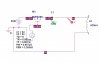
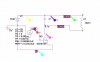
When I apply A sinusoidal to that ferrite rod from a KENWOOD signal generator, my system works properly. but I have to use my own signal generator for the final system. I designed a one and It worked well. But the problem is when I apply it to the rod, the voltage drops.

I decided that the low reactant of the coil may be the reason. But why did it work with the signal generator? What shall I do to this problem? I'll update my test results. Please give some comments. (If you no anything about 8038 ICs,pls share that also)
 

Attachments

  • 1.JPG
    1.JPG
    34.2 KB · Views: 207
  • 2.JPG
    2.JPG
    39.8 KB · Views: 197
  • 3.JPG
    3.JPG
    40.6 KB · Views: 194
I've forgotten to mention that in diagram 3 the point 1 shows a distorted/noise signal and point 2 shows a Sinusoidal.
 
The signal generator probably has a 50 ohm output impedance. The 8083 is tested with 1k ohm output impedance. You need a buffer amplifier on the 8083 output to drive a low impedance load.
 
Eventually, you've posted a picture and we can understand what you're doing!

So you want to build a 300kHz continious wave transmitter?

You don't need a linear amplifier, an RC filter or an 8038.

Just stick a capacitor in parallel with your ferrite rod coil and tune it to 300kHz. Feed it with a 300kHz squarewave using a MOSFET driven by the NE555 and it'll ring at 300kHz and produce a sinewave with very few harmonics.

I've done this before at 500kHz and it works perfectly.
 
Thank you so much! I have some English trouble in the reply. I don't know the way I Understood your system is correct or not. I have shown here how I understood your explanation.Is it correct?
 

Attachments

  • 4.JPG
    4.JPG
    31.9 KB · Views: 184
Last edited:
LC oscillator

I hope LC oscillator would do my work.(I hope that is what you mentioned in your idea hero)
 

Attachments

  • lc.gif
    lc.gif
    9.5 KB · Views: 151
Last edited:
Your receiving coil should also be tuned with a parallel capacitor.

Look at the datasheet for the very old 741 opamp:
1) Its output drops above only 9kHz.
2) At 300kHz its max gain is only about 3 when its load is 2k ohms or more.
 
Just drive the MOSFET from the 555.
 

Attachments

  • Simple CW Xmitter.GIF
    Simple CW Xmitter.GIF
    3.7 KB · Views: 168
Thank you for your reply hHero, I have simulated your cct using Orcad. But It doesn't show me the desired output??? Any clues?
 

Attachments

  • Schemetic.JPG
    Schemetic.JPG
    38.7 KB · Views: 242
  • Signal Graph.JPG
    Signal Graph.JPG
    171.8 KB · Views: 160
If you like pls go through the Orcad files folder given below.
Run the testma.dsn (schemetic 1,paGE 2) to get the above diagram
 
I have tried changing values for pulse width time, Frequency of mosfet driving pulse, Inductor values. But no change in the signal out
 
The capacitor and inductor values need to give a resonant frequency close to 300kHz. For example if you set L to 820:mu:H and C to 330pF, the resonant frequency is 306kHz which should be near enough.
 
Whatever I do in the Orcad no change in the output. I think it has not been programmed for the resonant part. Anyway I have tried a loooooooot of ways to create AC from DC. Every think failed. Your model looked like some SMPS(those bucks booosts) stuff. So I thought It may work. Anyway I'm going to try your one practically. But While I was doing some Buck stuff in the orcad simulation worked. Thats why I wonder it fails now. If your one also fails I'm in trouble. May god find me some other way. ;) thanks hero
 
Hi Hero, could you please explain me that how your system works such that it generates a sinusoidal? Any reference which could help me?
 
The inductor and capacitor form a resonant tank circuit that rings if the pulses applied to the MOSFET's gate are the same frequency or a harmonic of the resonant frequency.
 
Small correction

Hi Hero, I found out the diagram by randomly connecting components in Orcad Capture. So I hope this is what u've meant. Have a look at this thanks alot.
:)
 

Attachments

  • half success 1.JPG
    half success 1.JPG
    34.4 KB · Views: 138
  • half success 2.JPG
    half success 2.JPG
    107.7 KB · Views: 127
When adjusting Pulse time and Capacitor values I'm able to get a ALMOST STABLE signal. But the there is a voltage ripple. Have to check in the practical situation.
 
You need to make sure the frequency of the pulses at the MOSFET's gate is 300kHz or a subharmonic of that, i.e. 150kHz, 75kHz etc.
 
Status
Not open for further replies.

Latest threads

New Articles From Microcontroller Tips

Back
Top