Continue to Site

Welcome to our site!

Electro Tech is an online community (with over 170,000 members) who enjoy talking about and building electronic circuits, projects and gadgets. To participate you need to register. Registration is free. Click here to register now.

  • Welcome to our site! Electro Tech is an online community (with over 170,000 members) who enjoy talking about and building electronic circuits, projects and gadgets. To participate you need to register. Registration is free. Click here to register now.

Simple circuit question, NEED HELP!

Status
Not open for further replies.

idtkid

New Member
I need to wire up a simple circuit comprised of the following components.

5x Infrared LEDs 1.28v 30mA
1x preexisting IR camera/bluetooth circuit 3v 300mA

My question is can I wire these up to run off of 1 of 3 ac adapter that I have?

7.5v 700mA
5.2v 650mA
5.1v 700mA

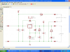
If so would someone please describe or a provide as schematic as to how to create this circuit? I would be so appreciative as this is a school project that needs to be completed soon. (I am a product designer creating a functional prototype for my thesis class) Thanks in advance for any help you may have
 
Hi idtkid

5 IR-LEDs of Uf=1.28V connected in series will require a total voltage of 6.4V.

Using the 7.5V power supply there will be 1.1V left to "kill". Applying Ohms law the current limiting resistor must be (US-UF)/IF, (Supply voltage-LED forward voltage)/LED forward current))

(7.5V-6.4V)/0.03=36.333Ohm. Next higher standard resistor value is 39Ohm. Using that value the total LED current will decrease to 28.205mA, which is acceptable.

For the IR-camera use the same power supply and make a voltage regulator circuit using an LM317T (adjustable voltage regulator, 1A). The data sheet contains a suggestion for an adjustable power supply. Instead of using a potentiometer you might use a trimpot to obtain a fixed value output voltage of 3V.

Boncuk
 
So off the leads of the power supply I run a series chain of 5 LEDs started by a 39ohm (wattage?) resistor. I wire the voltage regulator circuit in after that? or off of the same leads? Thanks for your help, forgive me as I am awfully new to this.
 
Hi idtkid,

first one advise: please avoid double postings. It will confuse the forum members as well as yourself.

For power rating of the current limiting resistor use this formula:

P(W)=U(V)*I(A). In your case U=1.1V, I=0.0282. Go figure.

Here is a complete circuit for your power supply including a single sided PCB layout.

With P1 in the center position the output voltage should be around 2.57V. At 66% (right hand turn) the voltage should be exactly 3.0V.

Final adjustment: Adjust voltage without load to approx. 3.0V. Connect the camera and recheck output voltage. A small voltage drop might be compensated by turning P1 a bit more clockwise.

Important: This circuit has no reverse polarity protection. Check polarity before connecting - otherwise poof.

Boncuk
 

Attachments

  • PWR-SUPPLY.png
    PWR-SUPPLY.png
    56.8 KB · Views: 155
  • PWR-SUPPLY.zip
    24.2 KB · Views: 100
thank you sooo very much for the schematic! appreciate it big time! I will let you know of my results!
 
Status
Not open for further replies.

Latest threads

New Articles From Microcontroller Tips

Back
Top