Continue to Site

Welcome to our site!

Electro Tech is an online community (with over 170,000 members) who enjoy talking about and building electronic circuits, projects and gadgets. To participate you need to register. Registration is free. Click here to register now.

  • Welcome to our site! Electro Tech is an online community (with over 170,000 members) who enjoy talking about and building electronic circuits, projects and gadgets. To participate you need to register. Registration is free. Click here to register now.

Simplest method for Analog Voltage level-inversion

Status
Not open for further replies.

bob4bvm

Member
I am building a controller for a brushed DC motor. Would like to use a typical game console joystick to effect fwd/rev switching as well as the speed signal for each direction.
I am able to use photo-interrupters on the stick to signal fwd & rev.
However using the 10K pot on the joystick as a speed ref input to my PWM motor controller is a bit trickier...

Assuming the stick's spring-center position is off, the pot wiper reads 5k (center pot)
Moving stick upward the wiper goes from 5K to 10K . Thats a useable increasing voltage from pot to increase the motor speed.
Moving stick downward the wiper goes from 5K to 0K , that would be a decreasing speed signal to the motor cntrllr.
Ideally I would like to find a way to make the pots' voltage signal go zero to max in each direction from the stick center

I was reading an old 2008 post from EricGibbs where he was describing use of the inverting input on a single-supply opamp which would reverse the voltage signal of 5-0V to 0-5V. But the schematic is no longer visible in that old post.

Appreciate any ideas, thanks
Bob
 
What supply voltage(s) do you have?
 
The solution is to use an opamp inverter with properties:
  • Amplification must be equal to -1
  • The "ground" input must be raised to the middle of the lowest/highest - that is 2.5V (regulated - you can use another opamp as voltage follower)
  • Since most opamps cannot function the full voltage range, you either must use a special variant that support rail-rail on both input and output. Alternatively you need a voltage supply to the opamp where Vcc > +5V and Vee < 0V.
 
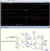
Below is the LTspice simulation of a circuit that, I think, does what you want:
It uses one quad rail-rail op amp package, along with a bunch of resistors to generate the desired function.

Note that the output green trace) goes from 5V at the 0% pot position (horizontal axis) to 0V at the 50% position, then back to 5V at the 100% pot position.
The blue trace is the pot output voltage versus pot wiper position, the red trace is the output of op amp U2, and the yellow trace is the output of U1.
The output of U1 and U2 are summed together by U4 to give the desired output.

The output is ratiometric so will track any variation in the supply voltage with zero out always occurring at the 50% point of the pot.

All resistors are ±1% type.

1637818628369.png
 
Last edited:
Of course you could do this in 8 pin micro with internal ADC and (DAC or PWM).

I think this would work -

1637797374685.png


The code blocks user sets up, as shown, are converted to Arduino code as shown in right hand window, by mblock.

Would take the ATTINY85 + 2 caps, one for ATTINY85 Vdd pin, one for PWM filter) and a resistor for PWM filter.
iu


1637792707843.png


Regards, Dana
 
Last edited:
Thanks all for the great ideas ! I was down to trying to attach a second (ganged) pot with opposite voltage polarity to the joystick to effect this. That has its own set of problems !
:)
Bob
 
Below is the LTspice simulation of a circuit that, I think, does what you want:
It uses one quad rail-rail op amp package, along with a bunch of resistors to generate the desired function.

Note that the output (blue trace) goes from 5V at the 0% pot position (0.0 on the horizontal axis) to 0V at the 50% position, then back to 5V at the 100% pot position.
The yellow trace is the pot output voltage versus pot wiper position, the green trace is the output of op amp U2, and the red trace is the output of U1.
The output of U1 and U2 are summed together by U4 to give the desired output.

The output is ratiometric so will track any variation in the supply voltage with zero out always occurring at the 50% point of the pot.

All resistors are ±1% type.

View attachment 134613
I really like this one as it solves another problem i had with interchanging the signal common when motor polarity reversed. This will provide on continuous signal over the motion of the Stick
I was not even aware of the 6484, will order some & test. Looks like the R-R operation is necessary to pull this off... I have alot of older stuff like TL084, LM308. etc but i don't suppose it is even worth a try with those (?)
Thx
Bob
 
I have alot of older stuff like TL084, LM308. etc but i don't suppose it is even worth a try with those (?)
Depends upon the output you need and the supply voltage used.
A standard (non rail-rail) op amp can typically go to only within about 2V of the supply voltage and 2V above ground (with a single supply voltage).
 
Depends upon the output you need and the supply voltage used.
A standard (non rail-rail) op amp can typically go to only within about 2V of the supply voltage and 2V above ground (with a single supply voltage).
Thanks. I will try a few others in your ckt while i wait for the 6484 to arrive. might be worth it to set up a bipolar supply for the older parts
 
might be worth it to set up a bipolar supply for the older parts
Problem is, the circuit depends upon the op amp outputs being clamped at the negative supply (ground) for proper operation, which rail-rail op amps do, so it won't work if the op amps have a negative supply.
 
Last edited:
Problem is, the circuit depends upon the op amp outputs being clamped at the negative supply (ground) for proper operation, which rail-rail op amps do, so it won't work if the op amps have a negative supply.
Well of course ...so much for that idea !

I will try some of my old parts with single supply to see how close to ground i can get. Not expecting any miracles, but i need the practice, plus i can pretty much just plug in the new parts to my breadboarded ckt when they arrive.
 
will try some of my old parts with single supply to see how close to ground i can get.
You might be able to get it to sorta work if you adjust the negative supply voltage (likely to around -1.5 to -2V) to just give a minimum op amp output of 0V.
 
You might be able to get it to sorta work if you adjust the negative supply voltage (likely to around -1.5 to -2V) to just give a minimum op amp output of 0V.
Yeah, as i was thinking. I'll play around with it & see what i get. Nothing lost in trying, I might even learn something :)
 
Below is the LTspice simulation of a circuit that, I think, does what you want:
It uses one quad rail-rail op amp package, along with a bunch of resistors to generate the desired function.

Note that the output green trace) goes from 5V at the 0% pot position (horizontal axis) to 0V at the 50% position, then back to 5V at the 100% pot position.
The blue trace is the pot output voltage versus pot wiper position, the red trace is the output of op amp U2, and the yellow trace is the output of U1.
The output of U1 and U2 are summed together by U4 to give the desired output.

The output is ratiometric so will track any variation in the supply voltage with zero out always occurring at the 50% point of the pot.

All resistors are ±1% type.

View attachment 134619
You also need a V+/2 comparator for direction with >1% hysteresis

The output shud control current, not Vavg of PWM using amplified 50mV shunt for Imax in a servo loop. Or else control Vavg with a conservative 3x Imax current limit loop.
 
You also need a V+/2 comparator for direction with >1% hysteresis
A better option would be a comparator connected between the internal Out1 & Out2 points in Crutschow's circuit, as the forward / reverse changeover will then track the zero speed point on the pot accurately, even if it's not a perfect mechanical centre point.
 
Below is the simulation using one of the four op amps to generate a direction output comparator signal (Dir, purple trace) as suggested by rjenkinsgb:
It should eliminate the need for the photo-interrupter circuits.
If you want the opposite polarity for the Dir signal, just reverse the inputs from Out1 and Out2 to the comparator.

1637948998012.png

 
Last edited:
Status
Not open for further replies.

Latest threads

New Articles From Microcontroller Tips

Back
Top