Electronman
New Member
Hi all.
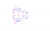
A question regarding to make a split (dual) power suply out of 78xx and 79xx.
I have a 7808 and a 7908 and want to get 14 to 15V max (+-7 to +-7.5) out of them.
Is the silicone rectifier diode the BEST why to do so? Any problem when performing? I want use this power supply with an op-amp as an inverting/noninverting amplifier. (a CMOS chip is presented in the said circuit).
Thanks
")