Continue to Site

Welcome to our site!

Electro Tech is an online community (with over 170,000 members) who enjoy talking about and building electronic circuits, projects and gadgets. To participate you need to register. Registration is free. Click here to register now.

  • Welcome to our site! Electro Tech is an online community (with over 170,000 members) who enjoy talking about and building electronic circuits, projects and gadgets. To participate you need to register. Registration is free. Click here to register now.

SVPWM Method

Status
Not open for further replies.

v1.5

Member
Hello to everyone.
I want to make a pmsm motor drive with FOC. I am currently doing the necessary research. I will later test this motor driver on a motor with sensor structure. but I want your help on some issues that come to my mind.
First of all, I need your information about a method that I am very curious about and cannot understand in research. How is the SVPWM method applied? How to apply SVPWM especially after inverse clark transformations. How is the signal applied to the inverter legs?
Although I studied many sources on this subject, I could not learn. Please help me.

In particular, in the pdf I added below, there are various information about this topic on pages 12 and 13. but I could not understand the connection of the example on page 13 with the values of Vr1, Vr2 and Vr3 obtained in the inverse clark transformation.
Especially what is described in figure 6-3 on page 13?
 

Attachments

  • Sensored-Encoder-Based)-Field-Oriented-Control-of-Three-Phase- Permanent- Magnet- Synchronous-...pdf
    584.8 KB · Views: 371
To run the PMSM there are at least two ways to handle the drive requirements.
A traditional control-loop 3-phase VF driver where we have the motor on a leash , 3-phase sine waves are sent to the motor and the motor follows the rotation of the electrical energy fields from the coils. The motor goes basically where we point it, with VF corrections to make it get on track using feedback from a encoder.
3ph_fixed_animate.gif


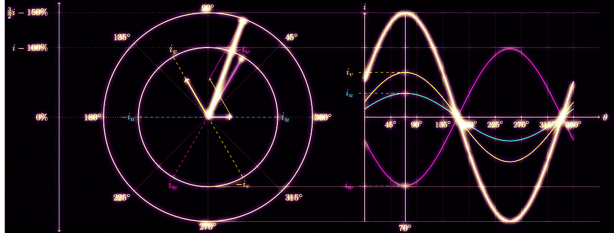
The modern FOC digital way is to have the motor on a solid tracked rail. We steer the motor at every instant (position calculation points) using a encoder or other shaft positioning method in a direct instant by instant application of the required fields to move the shaft to X encoder point and the next. FOC gives the three axis coordinates for the X position inside the motor and Space Vector Pulse Width Modulation is used to create the actual power waveform to drive the coils to that point.
image-asset.gif

This is a more in-depth explanation of how the needed waveform is synthesized.

 
Thank you. I know these sites and have reviewed them many times. but unfortunately I'm not even a dummy :banghead:. I understood the information you mentioned. The example in the 2nd .gif is very good. but here are two inverter representations below of that .gif , but I don't understand what they are. and I am very confused. Can you tell by giving an example? thank you.
 
What can you say about the switches in sector 1? Please help me analyze it.
sector 1 graph.PNG
 
Look at it another way?
The red phase PWM duty cycle output is the sine of the motor position (angle); 0 = 50% duty, positive or negative increasing or decreasing from that.

Blue is sin (angle + 120)'
Green is sin (angle + 240)'

The "switches" are showing the positive or negative output from those sine result. The horizontal lines on the PWM side are the sine results.
Red is above zero, green is below zero; red duty > 50%, green duty < 50%.

Multiply the sine results by a current control value before calculating the PWM value for current or torque control.
(And create a sine lookup table rather than doing trig calculations at runtime).
 
Thank you so much. Please let's clarify some issues..

Blue is sin (angle + 120)'
Green is sin (angle + 240)'
Are you talking about this topic below? Can you verify ?
1.PNG


The "switches" are showing the positive or negative output from those sine result.
At this point, I did not understand clearly what you said. What do you mean by "positive" and "negative"? I am confused that both inverter switch positions are different.
please correct if wrong;
For Theta = 31 degrees, which I shared as an example above, the switches on the left show red pwm duty decreasing (since it is greater than 30 degrees). The left key always points to positive vectors.
At the same time, the green pwm duty in the right switches is less than 50%. (as it is on the negative side) The keys on the right show only the vectors on the negative side.
Here we are now at the point where I cannot combine the clues. Why are the positions of the switches on the right and left different?

Multiply the sine results by a current control value before calculating the PWM value for current or torque control.
Can you explain in a little more detail? :sorry:
 
Are you talking about this topic below? Can you verify ?
No, just the top right quarter of the image you posted; the PWM levels & sawtooth part (and the one at the left of that for rotational angles).

"Zero" current (50% duty) is at the centre with positive above (> 50%) and negative below (< 50%).

The switches represent the PWM output combinations being on or off, with the duty cycles shown above the switches.

The left hand shows Red / U positive, with the other two phases negative; flux angle zero.

The right shows green negative (the inverse of it's 240' offset) with the other two positive, so flux angle 60' (240 - 180).

To give a target position between those two, they are alternated proportionally over two parts of a PWM cycle; the same idea as microstepping a stepper motor by powering two phases in different proportions to set the motor to an intermediate point.
 
Status
Not open for further replies.

Latest threads

New Articles From Microcontroller Tips

Back
Top