Continue to Site

Welcome to our site!

Electro Tech is an online community (with over 170,000 members) who enjoy talking about and building electronic circuits, projects and gadgets. To participate you need to register. Registration is free. Click here to register now.

  • Welcome to our site! Electro Tech is an online community (with over 170,000 members) who enjoy talking about and building electronic circuits, projects and gadgets. To participate you need to register. Registration is free. Click here to register now.

TDA 2030 need more info please

Status
Not open for further replies.

hobbyguy

Member
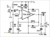
Ok in the image of the schematic has 100nF i read and they said that is also
0.1µF or is it 0.10µF and also the 220nF is it 0.22µF i just want to clarify that if is true.
And the R4 is it a 1ohm resistor, and the potentiometer is it a 22K...

The other question i have could this be power with two 9V battery.
Well thank you...
 

Attachments

  • TDA2030 14W.gif
    TDA2030 14W.gif
    6.9 KB · Views: 375
hi,
Those values are the same 100nF = 0.1uF 1R= 1ohm, I dont see a 22Kpot.??

The d/s states +/-6V min Vsupplies.
 

Attachments

  • AAesp03.gif
    AAesp03.gif
    13.5 KB · Views: 202
You can refer to the Single supply application circuit provided in the data sheet:

**broken link removed**

That shows how to connect the 22K pot at the input line. Here the +Vs is 28V for typical performance.
 

Attachments

  • TDA2030-circuits.jpg
    TDA2030-circuits.jpg
    22.1 KB · Views: 680
Last edited:
1nF = 1e-9 Farads. 1µF = 1e-6 Farads. Thus 100nF does indeed equal 0.1µF.
 
hi,
Those values are the same 100nF = 0.1uF 1R= 1ohm, I dont see a 22Kpot.??

The d/s states +/-6V min Vsupplies.

Thank you.... about the 22k pot i though it was the want that had the line in and it had 22k... but I'm sorry for the mistake i did.
 
So in the schematic that you gave me have to be power with a adapter 28V but how many Amp or mA do i need... and thank you for the new schematic how many output power would i be getting with this one... And the center from the pot would be connect it to the negative of the 1uF rite... Oh and the last one i see that the lines are crossing each other but are the ones that are really going together are with the dots correct. Thank you so much for your help.

You can refer to the Single supply application circuit provided in the data sheet:

**broken link removed**

That shows how to connect the 22K pot at the input line. Here the +Vs is 28V for typical performance.
 
Status
Not open for further replies.

Latest threads

New Articles From Microcontroller Tips

Back
Top