Continue to Site

Welcome to our site!

Electro Tech is an online community (with over 170,000 members) who enjoy talking about and building electronic circuits, projects and gadgets. To participate you need to register. Registration is free. Click here to register now.

  • Welcome to our site! Electro Tech is an online community (with over 170,000 members) who enjoy talking about and building electronic circuits, projects and gadgets. To participate you need to register. Registration is free. Click here to register now.

Test Oscillator

Status
Not open for further replies.

linguist

New Member
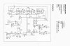
I have a small sine/squarewave Test Oscillator that the frequency range is to about 24kHz, I need to test something that requires 40 to 50kHz.

I have attached a schematic of the oscillator circuit, The frequency selector pot is ( P2
W100k) marked with a Red rectangle. Can I just use a 250k pot to increase the frequency range or will this cause issues?

Cheers
 

Attachments

  • Test Oscillator.jpg
    Test Oscillator.jpg
    426.3 KB · Views: 202
hi,
The Zener D2 is a 5.1V, the Freq pot varies the frequency control voltage from about 1.5V to 5V, so increasing the value of the pot will no effect on the frequency range.

Have you tried applying a control voltage of 6V at the Vcontrol connector, see how much change you get for the extra 1V.?

Also do you need the double frequency of the sine wave output or would doubling only the square wave output freq be OK.?
 
Last edited:
Hi eric, thanks for the reply.

I wasn't sure about applying extra control voltage but as you say an extra 1V might be worth a try.

It is the Sinewave I need for testing as long as it is still adjustable.

Cheers
 
Last edited:
Sorry for the double post,

I was just looking at the datasheet attached for the LM13600 not that I understand it correctly but I think it suggests that the maximum allowable control voltage is 5V? for the VCO.

Maybe I need to reconfigure some components to allow for a higher frequency sine output, not sure where to start with this though?

Or would it be a better solution to use a frequency doubler circuit after the Test Oscillator?

Cheers.
 

Attachments

  • LM13600.pdf
    636.1 KB · Views: 100
Last edited:
hi,
Look at this pdf, it should help in modifying the circuit.
 

Attachments

  • UsingOTAs2.pdf
    609 KB · Views: 167
The bias current for the transconductance amplifiers is alread as high as possible so leave the 5.1V as a max input to the 3.3k resistors.
Instead, reduce the value of the 820pf capacitors to increase the max frequency.
But the Japanese NJM4560 audio dual opamps cannot go higher than 30kHz without distorting the sine-wave into a triangle wave (slew rate limiting). Use Texas Instruments OPA2134 audio dual opamps instead that go up to 250kHz.
 
Thanks eric & audioguru,

The PDF & the information given is very helpful.

I will try a few things & order some new opamps as well.

Thanks again

Cheers
 
Status
Not open for further replies.

New Articles From Microcontroller Tips

Back
Top