Continue to Site

Welcome to our site!

Electro Tech is an online community (with over 170,000 members) who enjoy talking about and building electronic circuits, projects and gadgets. To participate you need to register. Registration is free. Click here to register now.

  • Welcome to our site! Electro Tech is an online community (with over 170,000 members) who enjoy talking about and building electronic circuits, projects and gadgets. To participate you need to register. Registration is free. Click here to register now.

Top250 won't work !

Status
Not open for further replies.

arvinfx

Member
I try to make a 48V 3A with TOP-250YN (Image of schematic is attached).
But output voltage is about 4 volts also I have to wait for about 1 minute to output capacitor achieves that voltage!


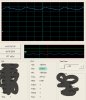
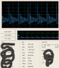
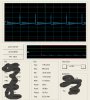
This is video of bias voltage reaction:
https://www.4shared.com/video/Hgl8LW7V/MOV03675.html


What is my problem guys?
 

Attachments

  • 13451285611.png
    13451285611.png
    40.8 KB · Views: 429
I will not watch the video because I need to sign up at 4sharded.com.

I know the TOP works well. What is the transformer turn ratio? What is the primary inductance?
 
I have reed datasheet and IC seems work correct and this reaction is normal ,But I don`t know why voltage on secondary won`t increase :confused:

The video and PIexpert file is attached.
 

Attachments

  • MOV03675.rar
    266.1 KB · Views: 161
  • 48V-3A.rar
    16.5 KB · Views: 147
I have asked 2 times about your transformer.
Why have you not answered? You will not get help like this.

"What is wrong but I will not tell you what I am doing."
 
Do you have a load? What load value? If you have a 3A load please make the load small. Maybe 100 ohms.

Please try removing C10 470uF to see if the voltage comes up better.

__________________________________________
When power is applied, current from R6, R7 charges up C5 to 5.8V, the PWM starts working, the IC pulls power from C5 and the voltage on C5 comes down to 4.8V where the PWM stops working. Now C5 starts charging up again. When the PWM is working power is moved form the primary to secondary. When the PWM is not working there is no power. I can see the PWM is (working, ----not working----, work, ----no work---) I do not see power moving to the secondary. Why; I can not see from here.

This is a typical 'start up problem' with power line PWMs.

__________________________________________
Look for:
Transformer has winding reversed. (phasing)
Transformer inductance is too low causing the IC to go into current limit.
Transformer saturation.
?????
 
Do you have a load? What load value? If you have a 3A load please make the load small. Maybe 100 ohms.

I have done it but output voltage goes down to 4v from 48v and transformer makes a sound like click click ...


Look for:
Transformer has winding reversed. (phasing)
Checked it was ok.

Transformer inductance is too low causing the IC to go into current limit.

At your first time that you asked I upaloded my PI Expert file, every thing is on it.
But your answer is:
Actual inductance of primary 370μH and leakage is 3μH


Transformer saturation.
Idon`t think so the core is ETD39 and as I see ( and you are able to see now :) )on scop the problem is value of PWM.

I really need your help, and also It is your kind :)
 

Attachments

  • C-pin.jpg
    C-pin.jpg
    141.5 KB · Views: 199
  • Primary.jpg
    Primary.jpg
    185.9 KB · Views: 188
  • Secondary.jpg
    Secondary.jpg
    160.8 KB · Views: 221
Last edited:
post 9:
Picture 1 probably is the output voltage.
Picture 2 and 3 (where is this)?

You have a file "48V.3A.UDS is that the PI Expert file? On this forum almost no one uses PI Expert. I do not have it on this computer.


I have attached the data sheet on the IC because it is hard to find.
 
Picture 1 is the output. The voltage is low. There is ripple at a low frequency. Maybe 10hz.

Picture 2 is the switch D to S. F=50khz. What is the on time of the switch?
 
Do you have a current probe? Can you see the current on the primary? The current should slope up at about 1Amp/uS.

0.8A=300V * 1uS/370uH or 0.8A/us
 
post 9:
Picture 1 probably is the output voltage.
Look at filename of each picture . First one is voltage of Pin-C second one is Primary voltage and third is Secondary voltage.


You have a file "48V.3A.UDS is that the PI Expert file? On this forum almost no one uses PI Expert. I do not have it on this computer.

Ok, then let me which part do you need to see I will take a picture from that part and put it on this page.

I will check the current of primary and say it .
 
I believe your on time is very short. Maybe 200nS or less. I can not see from your pictures.
Why is the on time very short? Probably because the current slopes up very fast to 6 amps.

If "X" is not connected then you might have this problem. The IC will current limit at 1.8A not 6A.

Have you talked to Power Int? They have good engineers to help you. They are very good for support. I have done that job in the past. Hopefully I will get that type of job again. You can send them to this forum for you information.

I am willing to help you.
 
I have talked to them :

**broken link removed**

X is connected to GND but I saw current curve by attached one ohm resistor between Vcc (+280) and transformer.
result was 2.2A
 
Last edited:
I have talked to them :

**broken link removed**

X is connected to GND but I saw current curve by attached one ohm resistor between Vcc (+280) and transformer.
result was 2.2A
At powerint you said you cut the "C" input. The IC gets power from the opto isolator U2. With out U2 the IC can not run for more than mS. Pin "C" is feedback and power.

You said the primary current is 2.2A. Is it a "ramp"? At powerint.com you said 200nS. Here you have not said. I have asked before.

At powerint.com the engineer said the TL431 can not withstand 48 volts. You can add in series with R10 a 24V zener diode.
 
If the primary current is going from 0 to 2.2A in 200nS then you inductance appears to be close to 30uH not 370uH.

What diodes are you using for D1, D2, D3. Have you changed to different diodes? example: UF4004 is not a 1N4004!
 
Sorry I thought you see 200n on my scop pictures. 2.2A was my mistake becase I accidently found out I used a 10 ohms resistor! sorry it was my mistake.

I think my problem is hook-up I am working on it and it is going to be beter ,now I have 8% (1us instead of 200ns).
 
Status
Not open for further replies.

Latest threads

New Articles From Microcontroller Tips

Back
Top