Hi to everyone,
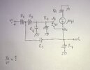
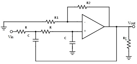
I am trying to anlyze a classic and vintage audio active equalizer using vacumm tubes inder, this units use severals filters with feedbacks loops in order to get a specific frequency response proposed for the manufacturer. My idea is to get the transfer function vo/vi of the all filters in order to modify to my needed and see the importance and performace of each circuits elements. I have done some work already using the classical network equations (Kirchoff and Network Theorems...) but the works is very hard to do solving systems of equations and mathematics simpllifications and many hours of hand and pen work with a lot of concentration. I would like to get some advises in order to know if does exist any theorical method more easier for get the transfer functions in these kind of electrical/electronical networks using various feedbacks loops in the same net??
I have attached one active filter drawing of the severals in cascaded found in the unit.
I appreciate any advise or help
Thanks anticipated
opacheco.