Continue to Site

Welcome to our site!

Electro Tech is an online community (with over 170,000 members) who enjoy talking about and building electronic circuits, projects and gadgets. To participate you need to register. Registration is free. Click here to register now.

  • Welcome to our site! Electro Tech is an online community (with over 170,000 members) who enjoy talking about and building electronic circuits, projects and gadgets. To participate you need to register. Registration is free. Click here to register now.

Transistor equivalent

Status
Not open for further replies.
Now, I know basic US rules and for the US, only the hot is switched for 120 V. We have split phase, so both hots have to be switched.

I THINK that once it's in a piece of equipment, you can fuse the neutral or switch the neutral. If i purchased a 120 VAC appliance wih a polarized plug, only the HOT would be switched.

If I bought a 120/250 50/60 Hz gizmo, it's likely that the neutral is switched and the device has a 3 prong or grounded cord.
e.g. https://www.te.com/commerce/Documen...CBS1&DocType=Customer+Drawing&DocLang=English

I know there's some weirdness that happens when larger power stuff is built for the US/uk markets.

So, not sure what the usual deal is in the uk or Vietnam for that matter. The US has basically a centertapped 120-0-120 transformer at the home. The center tap is neutral. The uk, I believe has a single secondary where one side is the neutral.

So, in the US we still have a single phase distribution, but the secondary is sometimes called split-phase.
 
My hi-fi receiver bass and treble tone controls are usually set to flat but sometimes I turn up the treble for a muffled TV show. I do not have a sub-woofer but have pretty good speakers with 8" woofers in sealed enclosures that resonate at 60Hz. I built a bass boost circuit that begins boosting at 60Hz and ends at 30Hz with +10dB. Visitors say they hear and feel vibrations from my "sub-woofer" but cannot find it.
 
Now, I know basic US rules and for the US, only the hot is switched for 120 V. We have split phase, so both hots have to be switched.

I THINK that once it's in a piece of equipment, you can fuse the neutral or switch the neutral. If i purchased a 120 VAC appliance wih a polarized plug, only the HOT would be switched.

If I bought a 120/250 50/60 Hz gizmo, it's likely that the neutral is switched and the device has a 3 prong or grounded cord.
e.g. https://www.te.com/commerce/Documen...CBS1&DocType=Customer+Drawing&DocLang=English

I know there's some weirdness that happens when larger power stuff is built for the US/uk markets.

So, not sure what the usual deal is in the uk or Vietnam for that matter. The US has basically a centertapped 120-0-120 transformer at the home. The center tap is neutral. The uk, I believe has a single secondary where one side is the neutral.

So, in the US we still have a single phase distribution, but the secondary is sometimes called split-phase.

UK is Live 230V, 50Hz, Neutral, which is earthed by the utility company somewhwere, and Earth. The UK uses a three pin plug with a longer and larger earth pin. The normal domestic sockets are rated at 13A, although not fused.

There are two types of equipment, classA and class B (I think). Class A has to have an earth wire and the parts accessable by humans must be earthed. Class B has doubloe insulated mains transformewrs/ mains isolation and can get away with just live and neutral wires.

On equipments, you can just switch off the live supply, but pro equipments always switch both Live and Neutral. There are some equipments where live and neutral must be switched.

The UK Consumer Units (Fuse box) have MCBs (Minature Circuit Breakers) which detect an over current for each circuit and there is an RCD (Residual current Detector) which ensures the the Live and neutral Currents match- if not they trip. Both are resetable.

The US voltage seems much more sensible to me at 110V, and the frequency of 60Hz is better than 50Hz too, but more audable. Also 110V does involve twicw the weight of copper for a given power. Not sure how split phase works but I understand it is safer.
 
Last edited:
My hi-fi receiver bass and treble tone controls are usually set to flat but sometimes I turn up the treble for a muffled TV show. I do not have a sub-woofer but have pretty good speakers with 8" woofers in sealed enclosures that resonate at 60Hz. I built a bass boost circuit that begins boosting at 60Hz and ends at 30Hz with +10dB. Visitors say they hear and feel vibrations from my "sub-woofer" but cannot find it.

Intresting- where did you put the bass boost circuit in the RX? You can transform the sound of speakers by your approach. The speaker X over does this to an extent but, of course, it can't provide power. One of our lot built a couple of large three chassis speakers. He also designed and built three amps to drive the woofer, squaker, and tweeter individually and directly. All the crossing over was done in the amps. The guy was a filter guru and the whole thing was phase linear- so he said. The system produced a very clean sound with extended base, probably by doing similar to you.
 
My bass boost circuit input is from the tape out from the receiver and feeds into the tape in. Remember magnetic tape? Chrome tape? Dolby noise reduction?
 
My bass boost circuit input is from the tape out from the receiver and feeds into the tape in. Remember magnetic tape? Chrome tape? Dolby noise reduction?
Yes remember it well- NAB characteristic? Then there was the RIAA phono characteristic- what fun!
 
split phase or single phase
Just have like 9 kV on the primary and 240 CT on the secondary.

The primary has one side grounded and the center tap of the secondary is grounded.

The secondary center tap should be grounded at the "ground rod" for the building.
Thus, you end up with two 120 V circuits 180 degrees out of phase with a shared common.
-90 0 deg +90
L1 N L2 (dunno which is which)

240 V single phase stuff can have L1 L2 and N and G

What has been wierd is the way all electric dryers have been wired in the past. Now, they require a 4-wire circuit.

Electric Water heaters typically us L1 L2 and G.

So, for us, the typical 240 V stuff is:
The outside air conditioner. Not the inside blower.
Electric furnace heat may be 240
Stoves 240 V
Washer - usually 120 - The new fangled front loaders usually require a separate circuit
All electric dryers - 240 V, Gas dryers 120 V.

Kitchens, I think now must have a few 120 V 20 Amp circuits.

I don;t know the rules for GFCI's (RCB's) and AFCI's (Arc Fault Circuit Breakers). "Tamper proof - kid proof" outlets have begun to come into play. These are outlets where you cannot insert something into just one side. When I re-painted a bedroom with 50's style outlets, they were all changed to grounded tamper proof outlets. I still have fuses, no breakers. GFCI's are on outdoor circuits only. They should be in the bathroom and kitchens. Your effectively grandfathered until a major remodel.
Bathroom: The toothbrush chargers are double insulated and my hair dryer has a cord GFCI, so I'm not worried.
 
Hmm! sounds complicated in the States- maybe UK's deciscion to go for 230V wasn't so bad after all. Who supplies all the different voltages? We just have one armoured underground cable comming itnto the house. That connects the the electric company board into a 60 to 100A fuse and then a meter. We have tails comming from the meter which are then the consumers responsibility. Any more power is provided by three phase. But that is very expensive to install.

The regulations are very strict now, but at one time anything went. They are very keen on earth bonding. So there is thick green and yellow striped cable all over the place. I used to do my own house wiring but it is not allowed now.

Our outlets have a sliding barrier inside so that when the plug is not plugged in the socket is blanked off. The earth pin on the plug is longer like I said and that moves the barrier out of the way.

Even class B items (2 pin) need a dummy earth pin, normally plastic. The damn things are really badly designed and snap off as with my Nexus 5 cell phone charger. At the moment I have an artists paint brush stuffed in the earth socket so that I can plug the charger in.:arghh:
 
Last edited:
Are you saying that you want to use the NE5532. If so, no problems. Let me know and I will have a look at that.


The audio power amp can be used without a preamp; it all depends on your signal source.


OK , but tone controls equilisers etc, not good for hifi.
Agree. I really dont want to use a preamp because it can turn hi-fi into low-fi, but the audio source weak like phono or sth... it may be a problem. I think if the source too weak, I make preamp from transistors (hifi opamp like OPA2134 too expensive, 89000VND but I cant sure about quality)
 
A phonograph pre-amp is a special bread because of equalization. The most common is RIAA.

Cartridges are either:
a) Ceramic (low-fi high output)
b) Moving magnet
c) Moving coil (low output and I think the best sounding)
 
Have overhead power lines from the 60's. The transformer feeds about 4 houses with about 100 A of 240 V. The fuse is on the primary side. The secondaries run to the meter first and then the "fuse box"/"breaker box" where there is a main fuse.

The power companies have upgraded to "smart meters". Rumor has it, they can disconnect power remotely. Meters are read by a Zigbee network.
The trend was to put a disconnect on the outside of the house. So, it's a fire company thing that power can easily be disconnected.

For emergency home access (fire/rescue), there is this thing called a "knoxbox" https://www.knoxbox.com/ that many business have, but homeowner can have it too. The fire company has "controlled access" to the box. The keys are "dispensed" so to speak. So, I can't use it to put a spare key because I don't have access to the box which would contain keys. It saves the fire company from breaking down the door.
 
A phonograph pre-amp is a special bread because of equalization. The most common is RIAA.

Cartridges are either:
a) Ceramic (low-fi high output)
b) Moving magnet
c) Moving coil (low output and I think the best sounding)​

Fully agree but (c) is better by a mile and a half. Moving coil cartridges typically have an output of 3mV at 1Khz, 3oouV at 20Hz and 30mV at 20 Khz. Some of the esoteric types can divide that by three though.

That is not to say that there is not some fine moving magnet types, and their big advantage is 10x the output.

Because moving coil are high end the manufacturers also make the stylus high end and you get all sorts of materials and shapes, starting with elliptical. In the days when I was experimented with moving coil a shape called Shibata or similar was the wave.

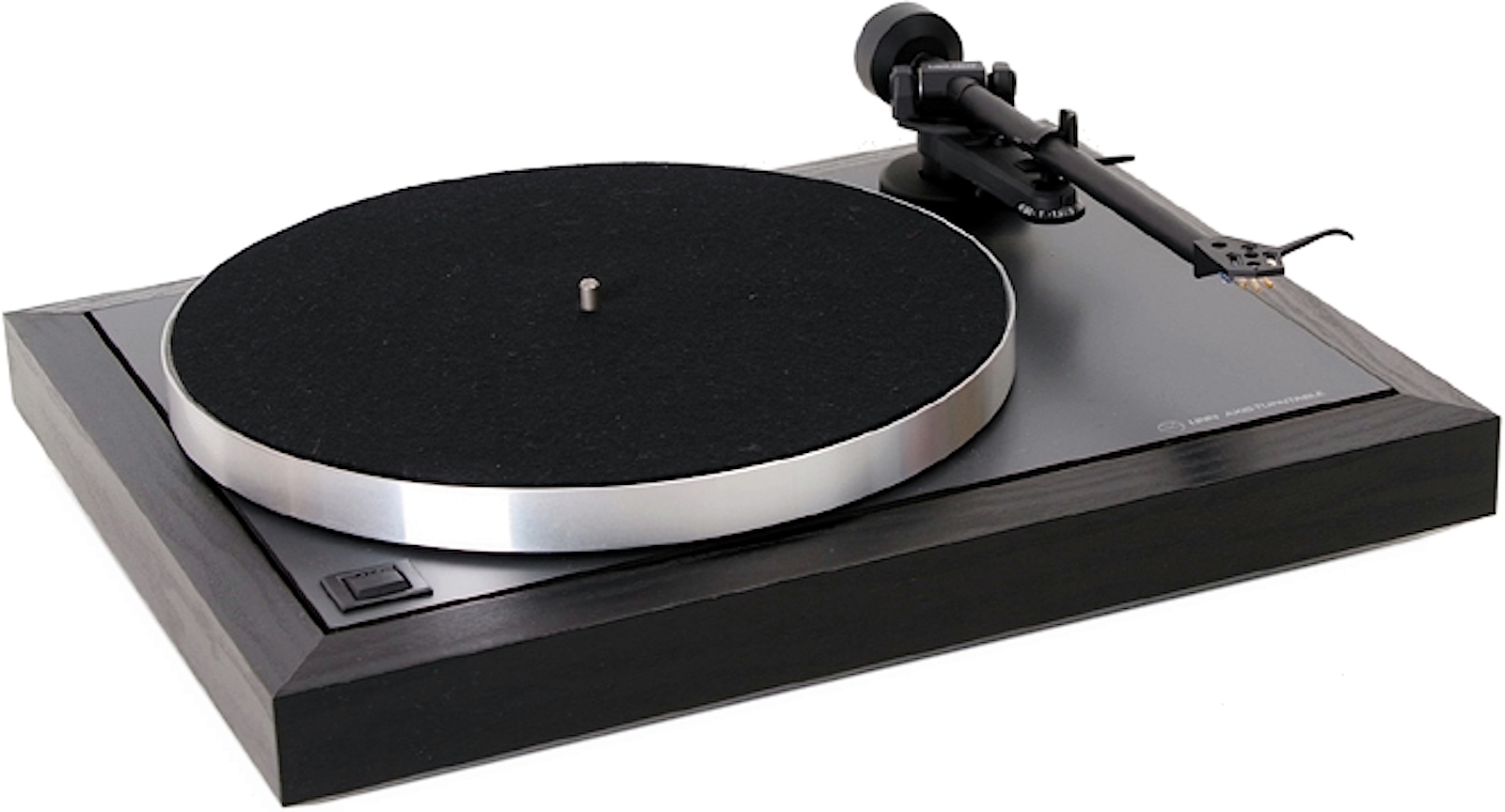
Once you go to moving coil and other low output cartridges then you need to start spending money: turntable, pickup arm, and cables. My favourite was a Linn Sondek and LP_2 arm- never owned them though. I even considered buying one on Ebay- just as an ornament to look at. Image shows a modern version:


A good cartrige in a good setup makes your record (disk) collection sound completely different. The stylus seems to get to the root of the music and produces a much more natural detailed and dynamic sound. As I have said before, it completely changed my library of records. The other thing that surprised me was the way that a good cartridge cuts across noise and scratches etc on the disk, and gets right into the grove to the music.

But such a low output voltage means that the MC amp has to have some magic built into it. I have said that audio electronics is 50% engineering and 50% black magic, well MC amps are 5% engineering and 90% art; the missing 5%- not sure. Along with my homemade amp I had access to a pretty good set up. I spent a long time trying to make a MC amp that equalled the pro MC stage- not a chance!

The odd thing, that I hadn't appreciated at the time, is that noise is not just noise- it causes distortion, presumably by intermodulation.

I much prefer the modern digital approach and do all my listening at the moment via a DAC amp and phones, but a good vinyl set up definitely has something that digital doesn't.​
 
Last edited:
Agree. I really dont want to use a preamp because it can turn hi-fi into low-fi, but the audio source weak like phono or sth... it may be a problem. I think if the source too weak, I make preamp from transistors (hifi opamp like OPA2134 too expensive, 89000VND but I cant sure about quality)
Hi Nikolai,

Can I advise to first build the power amp and PSU and forget the preamp for the time being. On balance, best now to go for an integrated amp with both channels and PSU in one case. Make the case solid with plenty of heatsinking- too much would be good. Concentrate especially on the construction of the case. Make it big and beautiful. Use the biggest transformer you can lay your hands on and winding pairs of 2x 18V up to 2x 70V or the best you can. That way you will be able to up the amp power in the future with the minimum of fuss. Be prepared to, move/change the orientation of/screen, the transformer to elliminate hum pick-up.

Stage 1 is to get the PSU and case design done, leaving plenty of room for the preamp PCB, power amp PCB and heat sinks. This is the cornerstone of any good amp. Like with speaker cabinets, the more solid the better. Also think about the case as a mechanism for heat dissipation.

Once you have the foundations laid you can go on to build your house. The beauty of this approach is that there is no nugatory work- you just keep experimenting and upgradeing and building and improving using the same case and PSU. The other approach is to build a case and power supply, then ditch that and build another case and PSU for your next wonder amp, and so on. Just to emphasise THE CASE AND PSU are fundamental to the success of your project and future adventures in audio engineering- do it once and do it the best you can.

When you first switch the audio power amp on the chances are it will not work properly- they seldom do. Be prepared for fault finding and changing the layout, etc to prevent instability, noise and hum pick up etc. The amp has a clossal gain and even a mV heare and there can cause problems. The commercial boys spen a lot of time getting this aspect right. ming you they have to ensure that all production amps work reliably- you have a big advantage as you will be dealing with just one amp which is fully under your control.

On to premaps. The NE5532 will sound fine, as will the TL072. Like I said, if you are not happy, you can fit any amp you like, if you have a turn pin socket for the opamp that is. By the way, the Ne5532, and probably most of the audiophile opamps, will just plug in with no mods. The audio boys have a name ffor changing chips: opamp fettling, or something like that.

Finally can I say this to you- don't chase impossible dreams. It is a danger when you are young- I did the same. The end result was that nothing ever got completed.
 
Last edited:
About the power amp circuit that I posted- it may look complicated but I have put in things that not only will make it sound good but with a good layout (you noted the earth lines etc that 'seem to have gone wrong'), but should be well behaved. It also has an architecture that is well proven and suitable for many simple upgrades: output transistors, driver transistors, longtailed pair transistors, audiophile resistors and capacitors, additional circuit functions that I have left out for simplicity. The other thing is that you can increase the power output in essence by simply increasing the supply rails- providing the components will take the extra voltage/currents that is. The message is don't be put off by the apparent complexity.
 
I've had all three and the MC I like the best. It's my current and probably last.

Yeah, once you have heard moving coil there is no going back. I experienced five cartridges types:

(1) Moving armature (or simiar). Not sure how it worked but for the old 78s. Very high output and used to tear the grove to pieces, like the original non electronic horn types
(2) Xtal (common in valve(tube) portable record (disk) players of the 1950s to 1970s (1 volt output?). My first 'hifi' was a pair of WWII bomber pilots earphones connected directly to an xtal cartrideg- sounded fantastic!
(3) Ceramic (Sonotone 9TAHC- still remember the number)
(4) Moving magnet (Shure M75ED2- solid clinical and once it got in the grove never came out)
(5) Moving coil (Audio Technica ATF5 & ATF3 beautiful but a bit delicate- 2 written off)

I simply could not afford/prepared to pay for a half decent MC set up, especially as I had already effectively paid for my son's system, and listend to reel-to reel most of the time- another topic for discussion!
 
My core system for a number of years was:

(1) Home-made amp in a continuous state of mods but it was in domestoc management acceptable (DMA) form: self-made chassis, venered sleeve, black front panel and custom turned ally knobs.
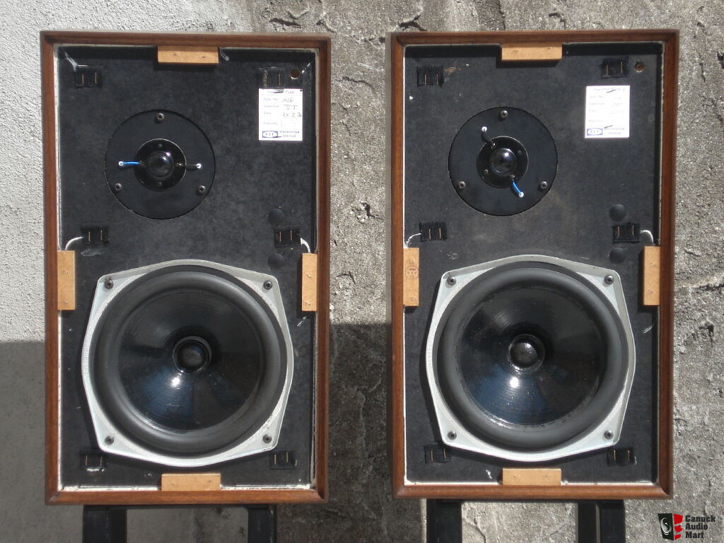
(2) Speakers based on the KEF Coral twin driver set up- sealed braced cabinet, 8 inch KEF B200 bass/mid and 1 inch Elac ally dome tweeter. Veneer matching amp
(3) Pioneer PL12D record deck with Shure M75ED II moving magnet cartridge.
(4) Tape deck Tanberg (an on going progect that never got any further than the workshop was a busted Revox deck. I repaired the deck and was building the electronics to suit but somehow it all got lost in a house move).
(5) Phones: Peerless PMB6. electro planar

**broken link removed**

755775-kef_chorale_speakers_beautiful_sound_and_condition.jpg


My son's system at the time was :

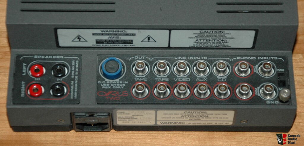
(1) Amp: Mission Cyrus II, 40W but 20A current capability (I think). Separate PSX2 PSU.
(2) Speakers: Epos ESP14s. Custom 6.5 inch bass/mid driver and custom 1 inch metal dome tweeter. 1 capacitor and 1 resistor xover. Mounted on some good, but not overly expensive stands.
(3) Speaker cables: mid priced (can't remember make and model number)
(4) Record deck: Linn Axis with LVX+ arm and Audio Technica ATF5 MC cartridge

linn-axis.jpg


http://zstereo.co.uk/2013/09/23/linn-axis/

EPOS_ES14_02.JPG


http://www.stereophile.com/standloudspeakers/566/#rIDKDZYgulMJe6Cp.97

**broken link removed**


184333-mission_cyrus_two_integrated_amp.jpg


Signature2.jpg


mission-cyrus-psx-power-supply-extension-fur-cyrus-ii-verstarker_596565.png


Hell, did his system sound good. The bass was amazing, especially for such relatively small speakers: extended, articulate, and plenty of slam. The metal dome tweeter, also custom, was xtal clear and detailed to the extreme and could cut through to your brain if asked to. As I have said before, we did a megga system shoot-out at a friends big place in the country. Everyone smiled when my son, who was only about 17 at the time, se up this tiny amp and 'little' bookshelf speakers with their funny stands. They were in for a shock.

My son now has a Chord Amp and B&W Nautilus speakers, fed from an upmarket CD player via a Chord DAC. He also has the most amazing pair of headphones with equally good DAC amp. (he is a computer pro with his own company and has very good barter/buying skills- the speaker and amp were aquired in one of his many deals). I avoid listening to his stuff- I am happy with what I have got, and don't want to be dissolusioned again :(

PS: this post describes my view only- some people may not like the sound I have described. There are many diffent types of sound reproduction. At the end of the day, it is down to personal taste, and even at the time, there were much higher quality systems, although with correspondingly much higher costs too.
 

Attachments

  • Cyrus 2 service manual_mod_reduced_2015_12_07.pdf
    686.9 KB · Views: 1,145
Last edited:
Why I need 70V? I think only 24V (or 28V)

You only need 18V RMS for the first set-up. What I am saying is, if practical, allow for 70V RMS for all future upgrades. If it is awkward to do, no big deal. Just do what you can. When you wind the secondary use as thick wire as you can. 28V RMS will give a good upgrade path.

The 70V RMS is to give +- 100V supply rails, which some amps need, especially MOSFET types.

You can't have more than +- 25V supply rails on my suggested power amp because the the transistors, apart from the TIP B&Cs, won't take any more. Even so, apart from the TIPs, the two transistors in the voltage amplification stage (VAS), and the two TIP drivers are right on the edge.

Incidentally, some of the transistors are not at all critical and pretty much any small signal type will do. If you already have some transistors, post a list and I will let you know what is what.
 
Last edited:
Status
Not open for further replies.

Latest threads

Back
Top