Continue to Site

Welcome to our site!

Electro Tech is an online community (with over 170,000 members) who enjoy talking about and building electronic circuits, projects and gadgets. To participate you need to register. Registration is free. Click here to register now.

  • Welcome to our site! Electro Tech is an online community (with over 170,000 members) who enjoy talking about and building electronic circuits, projects and gadgets. To participate you need to register. Registration is free. Click here to register now.

U643B based falsher relay shunt resistor location?

pavjayt

Member
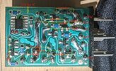
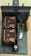
I am thinking of modifying my car's flasher relay that utilizes U643B, not sure if possible, but from its datasheet it seems one should be able to use it for any load >= 1W. In my car this is being used for for a total of 63W/side (3 bulbs) or 126W in Hazard warning mode. I tried to label all TH components that are on the other side of the board for reference including the pins for both relays (color coded). Hope someone can find the "shunt resistor" as shown in the IC datasheet or a way to modify this to stop hyperflashing when I switch to LED bulbs.
LS< = Left turn signal from switch
LS> = Left turn signal power to bulbs
HW = Hazard Warning signal from switch
thanks
 

Attachments

  • RElay.jpg
    RElay.jpg
    6.6 KB · Views: 40
  • Flasher Relay.jpg
    Flasher Relay.jpg
    659.5 KB · Views: 29
I can't easily work out what is happening when you have two relays in the flasher unit, and the data sheet shows the normal flasher unit with three terminals, and your flasher unit has many, most of which have functions that I do not understand.

My best guess is that the wire you have called "short" that is labelled nearest to "HW" is actually the shunt resistor. The data sheet for the IC calls for 30 mOhms, and it's not likely that could be achieved with that length of copper wire, but it could be that some other metal was used.

There are resistors like this one:-
https://uk.farnell.com/tt-electronics-welwyn/oar3-r030fi/resistor-1-0r030/dp/1200370
which are just a bit of metal.
 
The two relays are one for each side signals (left and right turn) or both when HW is activated.

The long Short highlihghted in the picture near HW is that thick metal strip seen in the picture attached
 

Attachments

  • PXL_20240502_215724155.jpg
    PXL_20240502_215724155.jpg
    953.3 KB · Views: 29
Great, makes sense. Will see if chaging it with a different value for LED power needs works for their proper flashing
 
In my experience, it is only the front and rear indicators that are rated at 21 W. The side repeaters are rated at a much lower power. That is what the data sheet of the IC shows. The flasher units will flash faster when there is only one of the 21 W lamps working. The flashing rate won't change if a side repeater fails, as its current is too small to be noticed.

If you are trying to get the flasher to detect if one of the LED indicators fails, you will have to make sure that the current taken by the side repeater is small compared to what the LED indicators take.

For instance, if you have 2 W LED indicators and still have 5 W side repeaters, the total power will be 2 + 2 + 5 = 9 W. If an indicator fails, the power will drop to 2 + 5 = 7 W. That is only a small ( 22% ) change and it will be difficult to adjust the resistor to get that to work correctly all the time. You have to allow for a change from about 12 V to about 14 V when the engine is running.

If you change the side repeater to LED as well, then it will be much easier to adjust the resistor. With 1 W side repeaters then the normal running is 5 W and a failed indicator will result in 3 W, so that is a 40% change and that is much easier to detect, and is about what the original IC was designed to detect.

You may need to have some resistance, maybe 1 kOhm, in parallel with indicators on each side of the car. The IC detects the start of flashing when the indicator switch is turned on. That is described in the data sheet section 4.7. The potential problem is that LED lights may not conduct at all when there is a low voltage across them, which can make if difficult for the IC to detect that the switch has operated. A resistor may help if that is the case.
 
Good info, will keep that in mind when I say replacing them. My car has 2x 21W bulbs in rear tail light assembly on each side 1x 21W in the front and as you said probably 5W side repeaters
 

Latest threads

New Articles From Microcontroller Tips

Back
Top