Electro Tech is an online community (with over 170,000 members) who enjoy talking about and building electronic circuits, projects and gadgets. To participate you need to register. Registration is free. Click here to register now.
Welcome to our site! Electro Tech is an online community (with over 170,000 members) who enjoy talking about and building electronic circuits, projects and gadgets. To participate you need to register. Registration is free. Click here to register now.
That inverter circuit does not work:
1) Its lower driver transistor is shorted.
2) The 2N3055 has a very poor max saturation voltage at 10A and is worse at higher currents so the max output power is 20A x 12V= 240W, not 500W as shown.
3) The circuit does not have any protection diodes.
4) The resistor in the oscillator is only 100 ohms. Texas Instruments recommends a minimum value of 10k ohms.
5) The capacitor in the oscillator has a value that is way too large. It is so large that a non-polar capacitor will be huge and expensive.
6) It uses two quad opamps instead of one LM358 dual opamp.
I helped fix it a few years ago but a circuit with Mosfets is much better.
Before going too far, you should try to find a transformer with a 12-0-12 rating of 200A. It will need to be wound with at least 12 mm diameter wire or larger. All 12V connections must use 12 mm wire, and need to be as short as possible.
If you find that, then look for a battery with a 250A continuous output. If you use a "heavy duty" auto battery (55 AH), it would be flat in 5 minutes but it will probably explode before then.
a 12-0-12V transformer is useless anyway because the peak output voltage will only be 220V which is 155V RMS which will drop even more under load. To get the required peak voltage, you need a 9-0-9V mains transformer with extra turns on the secondary to provide the full voltage at the full load.
If you want a 2kW inverter, increase the supply voltage to 48V and use a 30-0-30V mains transformer which will give a high enough peak voltage at full load.
I was thinking about that, too. A square wave as shown by OP is a bad idea anyway, because RMS voltage is pretty close to peak voltage. This may be pretty good for rectified loads such as a PC, but resistive loads like lamps get twice their rated power!
The peak voltage from a square-wave provides the same amount of power to a resistive load as the RMS voltage of a sine-wave. But the peak voltage of a square-wave is too low for most electonic items whose rectifier charges the main filter capacitor to a voltage very close to the peak.
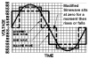
So many inverters produce a "modified sine-wave" that is a square-wave with two steps in it. The peak voltage of the steps is almost the same as a sine-wave.
Was it that long ago? https://www.aaroncake.net/forum/topic.asp?TOPIC_ID=6997&whichpage=3
Of course the better design would be a DC-DC convertor running at a few hundred Khz and then chopping the high voltage DC back into AC. It would make the transformer much lighter than the 2KW 50Hz monster required by these simpler circuits. Myself, I'd just buy a 3KW one at Canadian Tire for $500 and be done with it, but I only need 115Vac. Certainly cheaper than trying to find a 3KW 60Hz transformer!
Some 220V ones: https://www.litewave.co.uk/limousine_inverters.asp
I was thinking about that, too. A square wave as shown by OP is a bad idea anyway, because RMS voltage is pretty close to peak voltage. This may be pretty good for rectified loads such as a PC, but resistive loads like lamps get twice their rated power!
You get round that by reducing the duty cycle; i.e. building a modified sinewave inverter so the peak voltage will be 330V and the RMS voltage will be 230V. That way both rectified and resistive loads will be happy.
This site uses cookies to help personalise content, tailor your experience and to keep you logged in if you register.
By continuing to use this site, you are consenting to our use of cookies.