Hi,
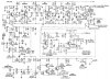
I purchase a few 5.5 MHz coils from **broken link removed** in order to attempt building a PAL B/G TV transmitter following the instruction at this website **broken link removed**. The transmitter diagram is below:

The exact item which I purchased is "5.5 MHz IF coil, green, design G, square 7 mm". The website offers various designs for various transformer frequencies. However for 5.5 MHz, design G is the only available design:

I completed soldering the circuit on a stripboard and get the video section work without major issues. Well, the picture always rolls (vertical hold issues?) no matter how I adjust the trimmer for video modulation but I believe it is due to the incomplete circuit. The transmission is also very sensitive to the antenna position but I believe I can always adjust it later.
However, when I started to solder the IF transformer for the audio part (5.5 MHz is the audio subcarrier frequency for PAL B/G), I realized that my transformer is of design G (two pins on each side (primary/secondary) with a tuning capacitor on the primary side), while I need design A (three pins on primary side, 2 pins on secondary side with capacitor on primary side) in order to build this TV transmitter.
Any ideas how I can use the IF can I bought to complete this circuit, perhaps with some circuit modification?
Thanks
I purchase a few 5.5 MHz coils from **broken link removed** in order to attempt building a PAL B/G TV transmitter following the instruction at this website **broken link removed**. The transmitter diagram is below:
The exact item which I purchased is "5.5 MHz IF coil, green, design G, square 7 mm". The website offers various designs for various transformer frequencies. However for 5.5 MHz, design G is the only available design:
I completed soldering the circuit on a stripboard and get the video section work without major issues. Well, the picture always rolls (vertical hold issues?) no matter how I adjust the trimmer for video modulation but I believe it is due to the incomplete circuit. The transmission is also very sensitive to the antenna position but I believe I can always adjust it later.
However, when I started to solder the IF transformer for the audio part (5.5 MHz is the audio subcarrier frequency for PAL B/G), I realized that my transformer is of design G (two pins on each side (primary/secondary) with a tuning capacitor on the primary side), while I need design A (three pins on primary side, 2 pins on secondary side with capacitor on primary side) in order to build this TV transmitter.
Any ideas how I can use the IF can I bought to complete this circuit, perhaps with some circuit modification?
Thanks
Last edited:
")