Continue to Site

Welcome to our site!

Electro Tech is an online community (with over 170,000 members) who enjoy talking about and building electronic circuits, projects and gadgets. To participate you need to register. Registration is free. Click here to register now.

  • Welcome to our site! Electro Tech is an online community (with over 170,000 members) who enjoy talking about and building electronic circuits, projects and gadgets. To participate you need to register. Registration is free. Click here to register now.

What voltage to apply to a 1.2V rechargeable battery?

Status
Not open for further replies.

J_Nichols

Member
Hi there, I am just experimenting with a simple circuit that recharges 1.2V 3000mAh AA battery. But I have not idea what is the correct voltage to apply to the battery to recharge it. Do I need to apply 1.2 Volts? Maybe a little bit more? This circuit recharges the battery using induction, so depending the distance the circuit receives more or less voltage.
 
Do I need to apply 1.2 Volts? Maybe a little bit more?
It depends on the battery chemistry.

For a NiCd or NiMH cell you should be applying a constant current.
For a 3000mAh cell, 300mA would be appropriate.
The voltage will be whatever is required to provide 300mA.

This circuit recharges the battery using induction,
? Care to explain how ?

JimB
 
It depends on the battery chemistry.

For a NiCd or NiMH cell you should be applying a constant current.
For a 3000mAh cell, 300mA would be appropriate.
The voltage will be whatever is required to provide 300mA.


? Care to explain how ?

JimB
Thanks for the answer.
The chemistry is Ni-MH.

I don't understand this:
"The voltage will be whatever is required to provide 300mA."
Do you mean that can I apply any voltage as long as the current is 300mA.?

Ok, I am going to explain.
I am using a small Tesla coil I bought on eBay a few weeks ago. The secondary of the Tesla coil produces high voltage and high frequency energy.
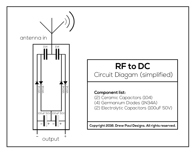
I use that HV-HF to feed a circuit that is basically composed of a few capacitors and diodes. This "rectifier" uses a single wire as an antenna to absorb the oscillations that are coming from the Tesla coil.

Circuit-Diagram-RF-to-DC.jpg
 
I am using a small Tesla coil I bought on eBay a few weeks ago

With that running and radiating for long periods to charge cells, you will probably be receiving a visit from the FCC or whatever your local radio regulator is - it's likely causing interference over quite an area...

Re. charging a cell, if the current is limited the voltage at the cell is likewise limited.
It will start at 1.2V and increase over time to near 1.5V

The hard part is deciding exactly when it is fully charged; you should use a voltage monitor circuit that senses when the voltage stops rising - or purpose-made charge controller.

Once it has reached full charge, if the current is less than 1/10th the capacity rating of the cell, a moderate excess time will not do any great harm, but higher than that will rapidly degrade the cell.

[Edit - typo].
 
Last edited:
With that running and radiating for long periods to charge cells, you will probably be receiving a visit from the FCC or whatever your local radio regulator is - it's likely causing interference over quite an area...

Re. charging a cell, if the current is limited the voltage at the cell is likewise limited.
It will start at 1.2V and increase over time to near 1.5V

The hard part is deciding exactly when it is fully charged; you should use a voltage monitor circuit that senses when the voltage stops rising - or purpose-made charge controller.

Once iot has reached full charge, if the current is less than 1/10th the capacity rating of the cell, a moderate excess time will not do any great harm, but higher than that will rapidly degrade the cell.
It's just a very small Tesla Coil. But thanks to give that advice about the radio regulator.

So you suggest to start charging it at 1.2V and increase over time near 1.5V, right?

About to know when it's fully charged I have purchased a battery meter. At the moment I have to disconnect the battery and check the charge manually.

I haven't measured how much current is flowing in the circuit, but I think it's less than 1/10th of the capacity of the cell.
 
So you suggest to start charging it at 1.2V and increase over time near 1.5V, right?
No.

You must limit the current into a battery. You don't set the voltage you set the current. Here is a picture of a typical bench power supply. Depending on what type of battery the voltage should never be above 1.5V so set the voltage know for 1.5V with no battery. Then short out the supply and set the current for 300mA. Now the supply will supply 300mA or less and 1.5V or less.
1549825888639.png

If you connect a discharged battery it will start out at 1.2V and the supply will limit the current to 300mA. The voltage will slowly work its way up to 1.5V. At that time the current will head down.
1549826140442.png

With your antenna it is likely you can't make 300mA so you don't have to limit the current from the antenna.
 
Thanks for the answer.
The chemistry is Ni-MH.

I don't understand this:
"The voltage will be whatever is required to provide 300mA."
Do you mean that can I apply any voltage as long as the current is 300mA.?

Ok, I am going to explain.
I am using a small Tesla coil I bought on eBay a few weeks ago. The secondary of the Tesla coil produces high voltage and high frequency energy.
I use that HV-HF to feed a circuit that is basically composed of a few capacitors and diodes. This "rectifier" uses a single wire as an antenna to absorb the oscillations that are coming from the Tesla coil.

Circuit-Diagram-RF-to-DC.jpg


Always nice to see 60+ year-old germanium diode technology solve a problem. Not that modern solutions don't exist but, hey, why not pick an old, leaky, low-current, expensive diode technology to make your project unique.
 
So you suggest to start charging it at 1.2V and increase over time near 1.5V, right?
What that means is, that if you limit the current, the battery voltage will be whatever it takes to charge at that current.
 
What that means is, that if you limit the current, the battery voltage will be whatever it takes to charge at that current.

To illustrate that have a look at post #8 in this thread:
https://www.electro-tech-online.com...ty-rechargable-batteries.146978/#post-1248053
It shows a NiMH battery being charged by a constant current, from a constant current charger circuit.
You will see that the voltage varies through the charging cycle.
At the end of the charging cycle, when the battery if "full" the voltage actually decreases. (The downside of the "hump" before the charger is turned off).

I am using a small Tesla coil I bought on eBay a few weeks ago. The secondary of the Tesla coil produces high voltage and high frequency energy.
I use that HV-HF to feed a circuit that is basically composed of a few capacitors and diodes. This "rectifier" uses a single wire as an antenna to absorb the oscillations that are coming from the Tesla coil.
That is going to be:
Very inefficient.
A generator of wideband RF (radio) interference which will make you most unpopular with your radio neighbours.
All in all a seriously bad idea.

JimB
 
J Nichols, did you notice that the radio receiver circuit has no coil to pickup the induction from the fairly low frequency tesla coil?
The tesla coil and the receiving coil must be VERY close together.
Did you notice that a battery is charged with current, not voltage since it limits its own voltage.
Go to www.batteryuniversity.com to learn about the details of charging a Ni-MH battery. Usually a battery charger IC is used to do it properly.
 
Status
Not open for further replies.

Latest threads

New Articles From Microcontroller Tips

Back
Top