Electro Tech is an online community (with over 170,000 members) who enjoy talking about and building electronic circuits, projects and gadgets. To participate you need to register. Registration is free. Click here to register now.
Welcome to our site! Electro Tech is an online community (with over 170,000 members) who enjoy talking about and building electronic circuits, projects and gadgets. To participate you need to register. Registration is free. Click here to register now.
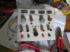
I already have a terminal for chassis, I just forgot to fit it on the mock-up.
What's the standard spacing? I assume this will enable me to plug in some sort of combo plug if I so desire...
Pretty good that throbs.
At first I thought make it smaller, but then you might want to twiddle the controls while looking at whats being powered, as I often do so a bit of room is good.
The only thing I'd consider is swapping the knobs and displays around, if you were adjusting you'd have to look under your hand/arm to see the display, commercial ones tend to have the displays at the top.
The other thing depeding on what you build, if its occasionaly mad or dangerous then you might benefit from a easily accessible main power switch that kills everything, for when your project is catching fire or zooming of the end of the bench.
I think spacing is 19mm, however I have a bannana plug to bnc which is tight so I think its 20mm, maybe theres metric and imperial spacings.
KISS beat you to it dr pepper, see #41
I'd put the controls at the top because the multiturn pots for the voltage controls clashed with the output heatsinks. I'm changing the board around anyway so I can move those.
A main power switch was part of the plan, I just completely forgot to include it on the panel! I was thinking also of individual channel on/off switches which will turn off the outputs - something else that got waylaid. Bit of a re-arrangement called for.
The layout I started off with had the controls alongside their respective meters, arranged voltage above current. (Again avoiding the clash with the heatsinks) I dropped that idea when I realised I could have a continuous display going across the front which looked much better. Where to fit the slide switches that change the current meters between set and measure is bothersome. Still not happy with them.
I finally ditched the Sziklai pair outputs btw, too many problems.
So anyway, re-arrangement again!
I think I'll use cap-head scews for the bezel and counter-bore the holes so they don't stand out so much.
Oops sorry, I didnt read the thread properly, yes #41 looks like a bought one.
The bench psu I made xx years ago has course and fine pots instead of a multiturn as at the time I didnt have enough pocket money to buy them, and having used it and another that has multiturn pots I have to say I like course/fine better, the principle reason is that I can see the ponter on the pot knobs, meaning if the supply is in current limit I know what the o/p voltage will go to one the current limit condition stops, that said building yourself means you can have it as you like.
Then use turns counting dials. Yup, more expense yet. I used Bournes Digi-pot which had a real digital display on the front for a project. One problem is, that it uses a BIG mounting hole.
Sounds expensive. My multiturn pots were 99p each! I picked a sub-optimal value for my saving though. Budget was extremely tight at that point.
My one attempt to make a coarse & fine control (a few years ago) was very non-linear - guess I didn't do it properly. It would be nice to do that with concentric controls if you can get linear ones.
I looked at those style knobs on eBay - counting turns in this context would be pretty meaningless so I didn't bother
74.43 of any currency is expensive I think!
I looked at those style knobs on eBay - counting turns in this context would be pretty meaningless so I didn't bother
74.43 of any currency is expensive I think!
For the application it was worth it,. 0-10 is effectively 0-100%. Limited use when you have dials.
What I find annoying is that some supplies may have a current limit, but you can't set it unless the supply is in current thus the ability to:
measure setpoint of V and I and output enable are useful,
CC/CV indication is also useful. When you use two, you get the added benefit of showing ON/OFF
Output enable (OE) is also useful
In this case the ability to gang OE may or may not be useful.
I've used both Course and Fine and Ten turn and my comments on preference would be the range of a supply.
When you have a 300 V supply operating at nominal 120 VDC, course and fine makes sense.
When you have a 30 V supply, 10 turn is OK.
The ability to TRACK is a very useful feature even if it isn't a true tracking supply. TRACK in this case means turn one knob and both change symetrically. it's NOT the real definition of a tracking power supply. A real tracking supply would keep GND 1/2 way between -V and +V at all times.
Thinking "off the wall", the ability to select 3.3 and 5 without having to twiddle, I think is a good idea. Implementing it, however, would be messy.
OVP or (Over Voltage Protection) could also be useful for a logic supply.
It has both tracking and parallel modes, voltage range is 0-38v. current limit is just diode-or'ed with the voltage one so no mode changing involved, it just happens. I may be mistaken but I think you helped design the tracking for it! Still haven't tested the parallel mode due to late design changes.
I opted to not have a cc/cv indicator because I didn't want the component count to increase even more. Though I think I'll re-visit the idea once this version is useable.
I know what you mean about real and not real tracking. I did one when still a teen which used a dual pot. Effective and simple but not very accurate!
I did think about adding some fixed voltages, but as you say, messy. Maybe for the MKII
Currency. Well, I proved my ignorance there! Surely there must be some large number at which the theory holds true?
I built a lm723 bench supply with integrating current limto for reduced noise, and a lcd display for volts, current, heatsink temp and power in watts, the details on on a thread here.
I plan time allowing to put a tracking switching reg on the input to it, an lm2576 or something.
Silly lengths were gone to to get a current limit led, I really wanted to know if the voltage wasnt being regulated, so the led in in series with the current limit circuit.
This site uses cookies to help personalise content, tailor your experience and to keep you logged in if you register.
By continuing to use this site, you are consenting to our use of cookies.