Continue to Site

Welcome to our site!

Electro Tech is an online community (with over 170,000 members) who enjoy talking about and building electronic circuits, projects and gadgets. To participate you need to register. Registration is free. Click here to register now.

  • Welcome to our site! Electro Tech is an online community (with over 170,000 members) who enjoy talking about and building electronic circuits, projects and gadgets. To participate you need to register. Registration is free. Click here to register now.

Screwwwwss

Status
Not open for further replies.
How about some clench studs, no head just flat.
 
Didn't know about them. Though looking for "clench studs" gets me horse related stuff, I think you mean these? **broken link removed**
Definite maybe :) though I wonder if the clinching part might crack the plastic? A bit of heat might be the thing.
So, I think I'm going stainless
Decided I don't like button heads

So either the self clinching studs, or countersunk socket heads, or counter-bored cap heads for me

Black would only look nice on a dark bezel - which might be too dark to see the meters properly. I have a green meter and blue meter on each channel, I think I need this colour: **broken link removed**

I'm sorry KISS, that's a really nice clock but you've got the screw-look I don't want! Maybe if they were black...
 
If you are interested in bezels, Digikey still stocks them @
https://www.digikey.com/product-search/en?keywords=led bezels.
I have also used 1/8" thick plexaglass a number of times, and have made the groves for flat head screws using a larger drill bit to do the counter sink part after I drilled the thru hole for mounting. I have a drill press that I set the speed for most plastics and it does a good job. I use minimum pressure and have no problem with counter sink holes
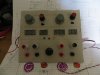
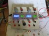
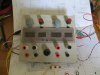
Nice, but they come in those two well known sizes - too large and too small!
Don't understand "groves for flat head screws"?
 
Yes clench studs are meant for steel chassis's's, if you make the hole a smidge bigger they'd probably be ok.
Allen head countersunk's might be better.
Unrelated I know but c/sunk allen heads make good security bolts if you jam a ball bearing in the allen socket, a 5mm hex key socket holds a 5mm ball tightly.
 
I MIGHT be able to paint some Torx screws and re-take a pic of the front panel. I may not have flat or semi-flat black. I THINK the Torx pan head screws I have are the same size as the clock panel. They are just Stainless instead of black.
 
KISS, you are going much too far!
I'm going to wait until I have more pieces of the panel before I make a final choice!
 
Nah. The pan head Torx are the right thread, but are too short. But I think all I have is Block Appliance Epoxy paint. I wish I had flat or semi-flat black. The Epoxy paint takes WAY to long to dry. Besides, I need to do some Black Epoxy touch up to something else anyway.
 
The MM5369. https://www.google.com/url?sa=t&rct...04.pdf&usg=AFQjCNEWsZow73oQiGT1NKP9BYZfdAJQbQ

I was unsuccessful trying to retro the chip for back-up purposes. Note the HP Logo on the rear panel. Our first names of the three of us that did the board per group of 3 or 4 are visible from the front. This was basically high school for me. A Boy Scout's Explorer's Post. We just had to PCB layout (just the traces) in 4x using black, blue and red tape, assemble and troubleshoot the clocks. So, I said, the first group's clock to work and the second assembled. I think we had a bad 5V regulator like many others and a missing display trace. It was tiny and it may have fell off.
 
The MM5369, that was it.

Speaking of other wonderful retro chips from National, do you remember the white noise generator, the MM5837?

I also built a pink-noise generator using one of those.
 
Disappointing reading the thread after reading the title, but then thought about it and realized it wasnt like i was gonna be able to add much to the discussion had been what I thought it was :D.
 
I just realised if you can divide 3.579 to 60hz, then in the uk colour burst 4.43mhz will divide to 50hz, and it does.

Anyway truss head in the uk I've seen listed as button head.
 
Disappointing reading the thread after reading the title, but then thought about it and realized it wasnt like i was gonna be able to add much to the discussion had been what I thought it was :D.
ROFL! Such a 15yo boy!
 
Speaking of other wonderful retro chips from National, do you remember the white noise generator, the MM5837?

Vaguely. I remember the dbx 2020 equalizer that had a pink noise source and a spectrum analyzer in it. I remember making a pink noise source too. My GF at the time made a "surff synthesizer" from a kit that sounded pretty good.
 
Ok here's a not very good mock up of the panel - it's made from a piece of cardboard with some grey paper stuck on it. It's a bit wonky because I did it all freehand. The perspex I actually use should be darker than the piece here but it gives an idea. I plan 4 screws along the top and 4 along the bottom of the piece.
 

Attachments

  • IMG_1881.jpg
    IMG_1881.jpg
    429.8 KB · Views: 144
  • IMG_1882.jpg
    IMG_1882.jpg
    302.6 KB · Views: 131
  • IMG_1883.jpg
    IMG_1883.jpg
    429.7 KB · Views: 139
I prefer a tiny bit more separation for each side, rather than a even spacing for everything. But that is a totally personal thing, will look great! I like the large to the back and small socket to the front, I have a cheapo chinky one thats the other way around and it drives me bonkers!! why be so stupid and do that?
 
Errrm, everything's at the front. Nothing at the back!
But anyway, I could make a wider panel. It was originally square because I wanted to keep the size down, which I didn't really like but was due to the spacings I needed in the case. I'm splitting up the main board so I've got more leeway now, so it's now shorter. Also I didn't want it to be significantly wider than the main board, but now I can see how it will (roughly) look I can see it needs more width. I was going to have the displays closer together so there would be a bigger gap in the middle and at either edge, but their circuit boards will overlap if they're closer than 10mm. I can file a bit off, but not much.
I was thinking I could use a layer of metallised plastic from an anti-static bag behind the bezel, save having to get the darker tinted stuff and stick with this piece of old record player top. That might look cool if it works.
 
Status
Not open for further replies.

Latest threads

New Articles From Microcontroller Tips

Back
Top