Continue to Site

Welcome to our site!

Electro Tech is an online community (with over 170,000 members) who enjoy talking about and building electronic circuits, projects and gadgets. To participate you need to register. Registration is free. Click here to register now.

  • Welcome to our site! Electro Tech is an online community (with over 170,000 members) who enjoy talking about and building electronic circuits, projects and gadgets. To participate you need to register. Registration is free. Click here to register now.

4volts to 14volts zenor diodes

Status
Not open for further replies.

jrautos

New Member
Hi i have a problem and need expert help please

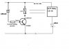
I have changed a filament lamp to a set of leds, the way it worked before was the lamp was half lit with 4v and then when the button is pressed it passes 14v and the lamp lights fully, my problem is that i know want it on or off, so i need to block the 4v and only let the 14v through.
I've tried a 12v 1.3w zenor but it doesn't let anything through so i tried a 7.5v and this work to a degree by blocking the 4v but it doesn't let the full 14 through it just gives me 5.8 volts

can anyone help as Im a little out of my depth to be honest and need expert help
 
Hi,

One way would be to drive a transistor with a zener and resistor, so when the voltage exceeds 7.5v it turns the transistor on and you get full voltage. If you need a circuit diagram that can be supplied for you also.
 
Last edited:
Hi thanks for the fast reply

would it be possible for you to draw this to show me how to make it up as i know only basic electronics

many thanks
 
Hello again,


Here is the basic circuit. The resistors depend on what kind of LED you are using. That circuit is based on 20ma LEDs. If you have higher power LEDs we'd have to change a few values, so you'll have to state what kind of LEDs you are using.
Typical transistor is 2N2222A or similar for the 20ma LED and might work up to 350ma with change of base resistor (R1). Resistor R3 is your LED current limiting resistor that you must have already selected.
That zener is your 7v zener or similar.
 

Attachments

  • LED_Contd-TurnOn-01.gif
    LED_Contd-TurnOn-01.gif
    2 KB · Views: 154
Last edited:
great just a little more info for you which might change a few things

the leds are in a unit which is sealed and can take 4volts to 14volts so i think the we might not need a resistor as i think they are built in to led set
 
Hello again,

Oh ok that's fine then. Do you know how much current your LEDs draw normally at around 14v ?
 
Hello again,

Ok then you may have to reduce the value of R1 to as low as 1k or so. You can check to make sure the transistor turns on fully by measuring the voltage from collector to emitter and it should be around 0.5 or even less.
 
Hello again,

Yes R2 can stay the same unless you use a bigger transistor and then lower it to 10k. You can use 10k with a smaller transistor too if you like.
 
Can the leds go after Q1 because i have 3 sets of leds and one -ve in the pack

3 +ve and one -ve for the set

nothing is simple
 
Hello again,

Can you take a picture or draw a picture so i can see exactly what you have there?
It sounds like you have three LEDs that have internal resistors so you can tie all three + terminals together, but i'd like to see your setup to be sure.
 
would this work

would this work
the relay uses about 150ma for the coil
 

Attachments

  • TransistorSwitch.jpg
    TransistorSwitch.jpg
    13.3 KB · Views: 113
Last edited:
Can you modify the original switching circuit by removing the resistor which supplied the reduced current to the orginal lamp? It likely is wired across the switch.
 
No wish I could, I've looked in to that it has a complex system with fault read outs

What is the original lamp WATT rating? (Or if you know it, how much current does it take to light the lamp to full brightness?)

Do you have access to a voltage supply outside of the original lamp driver, or do you have to do operate the LEDs from the original lamp driver?

When the lamp driver puts out 4V, do you have to waste the current that would have flowed in the original lamp (to keep from getting an ERROR)?

When the lamp driver puts out 12V, do you have to draw the same current as the original lamp even though the LEDs require much less current?
 
Last edited:
The original lamp was a 21watt.
Have to operate the leds the with original lamp driver
no do not have to waste the current as ive sorted the error msg
no do not have drawn the same current as old lamps and i get no errors with new leds
 
I suspect that the 4V you quoted is only there when the original lamp is connected; in other words, when the lamp is replaced with a much lower current load like the LEDs, that intermediate voltage goes up much higher. This makes it very difficult to design something without knowing the actual internal circuitry of the original lamp driver.

Could you do the following test? Suppose you disconnect all your LEDs. Now measure the lamp driver output voltage with no load both at the low level and at the high level.

Now connect a 50Ω 2W resistor in place of the LEDs/Lamp and measure the voltage across the 50Ω resistor both at the low level and at the high level. Report back with those four voltages I can suggest something...
 
I have already measured these

and at low power its around 4v with and with out load
and at high output its 14v with and with out load
 
Status
Not open for further replies.

Latest threads

New Articles From Microcontroller Tips

Back
Top