Continue to Site

Welcome to our site!

Electro Tech is an online community (with over 170,000 members) who enjoy talking about and building electronic circuits, projects and gadgets. To participate you need to register. Registration is free. Click here to register now.

  • Welcome to our site! Electro Tech is an online community (with over 170,000 members) who enjoy talking about and building electronic circuits, projects and gadgets. To participate you need to register. Registration is free. Click here to register now.

555 mono (restriction on Resistance value)

Status
Not open for further replies.

vinodquilon

Member
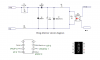
Find the attachment (555 mono schematic in Cadsoft Eagle.) . The purpose of the circuit is to turn on reed relay for 60sec, when
first ring_signal occurs. For that I have to use C= 100 uF & R= 560 K. But somewhere I have
read, in the design of 555 mono take R= 10 K to limit current through the internal transistor
to 1 mA.
Is it correct ? Can I use 560 K ?

It is my first time experience with Eagle to draw schematic. If someone notice any drawing faults
in my schematic, pls inform me to improve my drawing skill with Eagle.....
 

Attachments

  • 555MONO..pdf
    31.2 KB · Views: 235
560k is higher than 10k which means a lower current according to Ohm's law so why would exceed the maximum rating?

Incidentally I thought the minimum resistance was more like 470R but it depends on the power supply voltage.
 
For that I have to use C= 100 uF & R= 560 K. But somewhere I have
read, in the design of 555 mono take R= 10 K to limit current through the internal transistor
to 1 mA.....
My concern is the 100uF capacitor. That value probably will not work as the leakage resistance will not allow the capacitor to fully chargeso the timing will be off.
 
It depends on the capacitor.

If it's a tantalum then there should be no problem.

With large capacitor and resistance values, it's a good idea to factor the leakage current into the equation, the trouble is it's unpredictable and varies depending on the voltage across the capacitor so it can be a bit of a headache.
 
PICAXE-08 program

Simple PICAXE-08 program to create accurate 60 sec output time delay when first ring trigger occurs.

start:
if pin3=1 then holdoff
goto start

holdoff:
high 2
wait 60
low 2
goto start


See the attachment. Opto-couplers' output goes to IP 3 (pin no.4) of PICAXE-08.
I will connect IP/OP 2 (pin no.5) of PICAXE-08 to base of relay driving transistor BC547.
Thus I can accurately turn on relay for 60 sec when first ring signal comes.

I am newbie in the field of PIC microcontroller. Thanks for all help by IanP of edaboard.

I couldn't find any eagle libraries for PICAXE-08 on cadsoft. Does anyone have ?
 

Attachments

  • PIC..PNG
    PIC..PNG
    16.7 KB · Views: 141
Status
Not open for further replies.

Latest threads

New Articles From Microcontroller Tips

Back
Top