Continue to Site

Welcome to our site!

Electro Tech is an online community (with over 170,000 members) who enjoy talking about and building electronic circuits, projects and gadgets. To participate you need to register. Registration is free. Click here to register now.

  • Welcome to our site! Electro Tech is an online community (with over 170,000 members) who enjoy talking about and building electronic circuits, projects and gadgets. To participate you need to register. Registration is free. Click here to register now.

AD620 ECG problem

Status
Not open for further replies.

Fluffyboii

Active Member
This got out of hand so I had to ask here. I am aware I am being to dependent on this forum and it is not something I enjoy. I tried solving this problem multiple times with different approaches and failed.

The problem is no matter how much gain I apply and how I filter the signal I can not get anything identifiable that looks like a hear beat on the oscilloscope. Even in the highest sensitivity which is something like 10mV, it is just flat noise with no ECG like component when I connect the props to my arms and leg. I started with AD620 datasheet circuit
1673009730750.png

And went to something as simple as this after nothing I did work.
1673009496273.png

When bottom circuit is tested with a signal generator I can see that It works and I have about 500 times gain. I put a low pass filter to output to set 3db point about 50Hz. Even if I amplify the output 100 times more to a total 5000 with 2 more op amp stages I get nothing. I tried 3 different breadboards, different ICs and checked the connections to props and confirmed that cables weren't open or broken in places. Even with the simplest circuit I should see some fluctuations in voltage with that much gain but instead I usually get 50Hz line noise or something that is about 5-10Hz that is not a heartbeat. Using the top circuit causes op amp to saturate and hit one of the rails even though "ground" is set to the body. Nothing I tried works. At this point I believe the connections are not working because we are not using the cream thing that is supposed to be used with securing the connection to skin.
1673010291287.png

I can not proceed with the project without getting any signal. Any ideas what may be holding me back.
 
Well, the usual response from AG.
I think that the expression "susceptible to interference and oscillation" is more appropriate than "guarantees lots of interference and oscillation"

If the late Bob Pease can do his prototyping like this:

images


I am sure that Fluffy is OK with his plug-in breadboard and a handful of components.

JimB
Actually Bob did PCB protots as well. In his seminars he discussed applications
that needed guards around OpAmp inputs, and applications at high freq, so
those were not done as air protos. Air protos were also good for low C stray
problems in sone instances. There was no one rule for the way things were done.

Regards, Dana.
 
I can't really increase the gain of the AD620 since it also amplifies the DC off set of the electrodes and saturates with more than 10 gain. But I can get 100 gain at second stage and something like 2 at the last. Would that be more appropriate.
If the DC is common mode the IA will take care of that.

Regards, Dana.
 
I can't really increase the gain of the AD620 since it also amplifies the DC off set of the electrodes and saturates with more than 10 gain. But I can get 100 gain at second stage and something like 2 at the last. Would that be more appropriate.
The AD620 bias current quite low so it cannot be causing the problem, eg unbalanced
resistance of electrode and its interface.

Are the electrodes actually creating an unequal potential ? Whats causing the
Voffset ?


<<<< Quite Interesting


Regards, Dana.
 
I mentioned the breadboard antenna wires when I saw the very noisy (50Hz or 60Hz electricity?) 'scope photo.
I think I increased the gain too much end the 5V zener at the output ended up clipping the high voltage spike of the ECG signal so it looks like it is noisy on the oscilloscope display. I will get it right it normally is much leaner that photo showed up really bad.
The AD620 bias current quite low so it cannot be causing the problem, eg unbalanced
resistance of electrode and its interface.

Are the electrodes actually creating an unequal potential ? Whats causing the
Voffset ?


<<<< Quite Interesting


Regards, Dana.
I am not sure. I got 1000 gain of AD620 using two electrodes and it indeed should not have common voltage problems. Maybe the auxiliary op amp that is connected to it and leg is causing the issue. I can try balancing that ones bias currents by connecting the non inverting input to ground with a 12.5K resistor instead of directly grounding it. But I am sure that there is a increasing negative voltage bias that appears with increased gain of the AD620. I couldn't get it in oscilloscope screen in DC mode with Rgain 4.7K and it seemed like 6.8K was the limit which is about 7 times gain. This is pretty much how it is rn, I can draw a full schematic if you want. I need to experiment with it bit more to get it better tomorrow.
1674084834280.png
 
1674086135439.png

Here I draw it. I test the 4.7uF capacitors and they showed around 4.8uF so they are not inaccurate capacitors. 100n low pass capacitors were for 10K feedback resistors giving cutoff frequency of 160Hz but I changed the feedback resistors with 27K and now their cutoff frequency is about 60Hz instead I will correct it later, just wanted you to see the full circuit.
I think it has adequate filtering at least. 1M and 1K resistor is for making a voltage divider and getting the signal above 0V for the ADC in the Arduino to be able to work.
27X gain from both op amps is bit too much, last one is better of with 22K feedback resistor.
The summing action creates a 1/2 voltage divider and makes me lose some signal, not hard to see why it cuts it half. Also messes with cut off frequency of the filter. Should fix that, it is stupid of me.
Auxiliary op amp can have its grounded non inverting input grounded with a 1M resistor for better biasing I think and maybe if I do that I can increase AD620 gain without saturating it.
 
Last edited:
Your TL081 (U4) driving the leg has an input offset voltage that is up to 600 times(!) more than the original obsolete AD705 opamp. You need an offset voltage adjustment trimpot as is shown in the TL081 datasheet.

Adding a resistor to balance the input bias current is useless because the TL081 has the same almost ZERO input bias current (because the input transistors are Jfets) as the original AD705 opamp.

Electrolytic capacitors C2 and C3 might have temperature affected leakage current so they should be film type.

Is your C1 1nF or 1uF? 1uF will kill the needed cancellation of common-mode interference pickup because the patient is an antenna.
It is 1n. I will change the 4.7uF capacitors with 1u film capacitors then increase the 1M resistors accordingly.
IMG_20230119_200425.jpg

I modified the circuit to this right now, Signal stays above 0V as I wanted and I can get a good reading now:

1674149396917.png

When my friends gets the Arduino side done and we get a usable reading I will consider it done and will not bother too much about the rest since I will have to give back the electrodes and AD620 to school so I will not get to make it a permanent project.
 
Last edited:
Your new waveform is fairly noisy and the "T" or "U" peak is higher than normal.
Maybe because TL081 general purpose opamps are not low noise audio opamps?
Maybe because the opamps are not purchased from a good source?
 

Attachments

  • ECG.png
    ECG.png
    67.4 KB · Views: 217
Your new waveform is fairly noisy and the "T" or "U" peak is higher than normal.
Maybe because TL081 general purpose opamps are not low noise audio opamps?
Maybe because the opamps are not purchased from a good source?
I know those op amps are original since school gave them. We got something on the computer. Two sticky electrodes didn't introduce this distortion problem since it didn't require auxiliary op amp. I just used what school gave me, so I don't intend to use another op amp even though I got some possible alternatives myself. Deadline is tomorrow anyway. I would like to make this permanent for myself, maybe sometime later.
 

Attachments

  • DSCF4137.JPG
    12.8 MB · Views: 244
  • DSCF4138.JPG
    11.6 MB · Views: 237
The new waveforms on your computer have "digital steps".
The first waveform has slow "DC breathing".
The second waveform shows the heart beats stopping every 12th beat.
 
One ques, when you raised the G of the IA, you did not forget to lower
the other OpAmp Gs so that signal chain did not get overloaded ?

Design seems to scream out for an AGC loop of some kind. Driven by a peak
detector.......

Regards, Dana.
 
One ques, when you raised the G of the IA, you did not forget to lower
the other OpAmp Gs so that signal chain did not get overloaded ?

Design seems to scream out for an AGC loop of some kind. Driven by a peak
detector.......

Regards, Dana.
I did adjust gain accordingly. It is much less compared to 5200 I did last time. This time it was about 2500. The colored hand electrodes are just inconsistent I think.
The new waveforms on your computer have "digital steps".
The first waveform has slow "DC breathing".
The second waveform shows the heart beats stopping every 12th beat.
It wasn't that bad before when I test it on myself but when we did a final run with my friend that happened. I honestly don't know what can be done to get rid of it other than to add more useless high pass filters. Those are good ones btw we waited like 5 minutes for it to stabilize.
1674166076578.png
 
Last edited:
I survived a heart attack (2 stents were put in my heart arteries) 13 years ago and since I have had many ECG tests. All tests used 5 electrodes on my chest, none on my hands or arms. The waveforms looked normal, unlike yours.

Your highpass and lowpass filters are simple one-RC and have 2 filters in series producing a droopy corner and a gradual slope.
I am sorry. I don't know anything else to do, should I abandon all kinds of filtering and go back to two electrode + grounding leg solution. That one gave accurate waveform. I don't know how simple RC low pass or high pass filter can distort signal like that when the signal itself is far away in from cut off frequency.
 
I don't see any bypass caps at the supply pins.
For a single supply, there should be one (0.1uf) across the supply pins of each IC.
For a bipolar supply, there should be one (0.1uf) from each supply pin to ground.

The voltage divider should also have a 0.1u bypass cap.

Also use a well filtered supply.
Used 9V batteries so didn't gave too much importance to filtering caps. Removed the resistor voltage divider since it was pointless with the "DC breathing" that was going on.
 
A 9V battery has low power which causes its voltage to bounce up and down, needing good filtering or a voltage regulator.
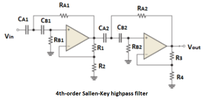
The 'DC breathing" will be reduced a lot if the highpass filters are active (with feedback) and have more orders for a sharp corner and much steeper slope.
Here is a suitable highpass filter:
 

Attachments

  • 4th order highpass.png
    4th order highpass.png
    53.8 KB · Views: 240
A 9V battery has low power which causes its voltage to bounce up and down, needing good filtering or a voltage regulator.
The 'DC breathing" will be reduced a lot if the highpass filters are active (with feedback) and have more orders for a sharp corner and much steeper slope.
Here is a suitable highpass filter:

The schematic calls it a Sallen-Key, its actually a VCVS filter topology :


Regards, Dana.
 
The VCVS filter was invented in 1955 and used vacuum tooobs or germanium transistors.
The Sallen-Key filter is newer using opamps.
 
Status
Not open for further replies.

Latest threads

New Articles From Microcontroller Tips

Back
Top