ccurtis
Well-Known Member
I don't follow your formulas at all, but that may be because we aren't on the same page with the numbers. The offset is the same as the sensors with no signal; 2.5V.
The formula is a sum-difference form of the function of your sensor inputs required to obtain your output, regardless of the op amp circuit resistor values. See attached. I assumed (perhaps incorrectly) you come up with something similar since you realise that you wanted to use a gain of four.

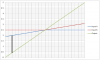
To start, 1.9 has to be subtracted from your sensor A (1.9 to 2.5v) output so that the circuit output starts from zero volts, giving a range of 0 to 0.6V. 1.9 must likewise be subtracted from your sensor B output (2.5 to 3.1v) so that it starts off from where sensor A output ends, giving a sensor B output of (0.6 to 1.2V). You then have as a result, a new offset voltage of 0.6 volts. To summarise in math terms we have: (A-1.9) + (B-1.9) - 0.6. We are not done, because you want 0-5V output, not 0-1.2V output, so that means applying a gain factor of 5/1.2 or 4.167 (your gain of 4 factor?). So then we have 4.167*[(A-1.9) + (B-1.9) - 0.6] which boils down to 4.167*A + 4.167*B - 18.333.
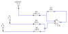
The only point I am making is that you will have to increase your negative offset voltage or apply gain to it to effect a largely greater subtraction term than you currently have. In your circuit configuration, that can be accomplished one way, by reducing the value of R3, but that also means adjusting the values of other resistor(s) to maintain the gain of 4 factor. It's a balancing act.
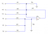
There are a few ways to configure such circuits. Here is one that should work. The two + inputs each have a gain of 4.167 (10K/2.4K) and the 2.5 voltage offset voltage has a gain of 7.333 (10K/1363.6) for an minus term of 18.3333 (2.5*7.3333).
Attachments
Last edited: