Continue to Site

Welcome to our site!

Electro Tech is an online community (with over 170,000 members) who enjoy talking about and building electronic circuits, projects and gadgets. To participate you need to register. Registration is free. Click here to register now.

  • Welcome to our site! Electro Tech is an online community (with over 170,000 members) who enjoy talking about and building electronic circuits, projects and gadgets. To participate you need to register. Registration is free. Click here to register now.

Automotive 6 Volt Generator Transistor Voltage Regulator

Status
Not open for further replies.
Just a thought - Max's regulator will also need a high current diode to prevent the battery feeding the armature when the engine is stopped or the output is below battery voltage.

Electromechanical regulators has a second relay for that function, double wound for both voltage control and current sensing, if I remember right?

The voltage coil would pull in once the output reached near maximum, then the current winding countered that if the battery started to feed back and dropped the relay out.

I can remember (vaguely!) back when I was a kid, converting old vehicles to negative earth by simply swapping the battery round, and pushing one of the contacts in the regulator together, to repolarise the dynamo field coil :D

The starter motor works fine of course anyway, as it's a series motor.
 
View attachment 120116

I have the main cutout diode shown in the hand drawn schematic earlier in this thread. I am wondering if it should go between the 7 VDC Rail at the top of Max's schematic and the car battery or somewhere else. I guess the .10 ohm resistor is probably more like 15 ohms, must have meant 10 ohms!
I am kind of wondering if the 3 reference input to the LM311 comparator is going to see enough voltage change relative to the 2 reference maybe it should go on the B+ side of the main diode or off of a .1 ohm resistor in series with the system load before the main diode?
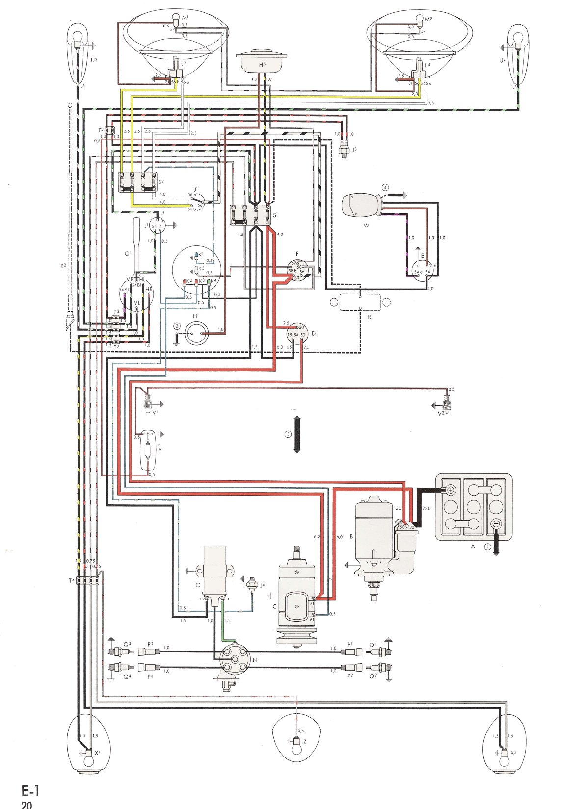
My car has a Negative Ground Electrical System:

bug60.jpg
 
Last edited:
Most motorcycle regulators work on the output because they use a permanent magnet rotor alternator and thus the field can't be regulated to control the voltage.
You don't want to try to regulate the output of an automotive alternator.
 
Max's circuit is functionally a kind of switching regulator; the field control transistor is driven by a comparator IC so either on or off.

It's not constant frequency PWM, more like a hit-and-miss governor.
But the flywheel diode across the field coil means the field current should decay relatively slowly between kicks, keeping a pretty constant output voltage.

The power dissipation should be quite low.
"rjenkinsgb"
I had missed this comment. I was wondering if it would regulate or switch. I already ordered a 3K 10 turn pot to find out.
Not sure I understand how a diode across the field will help the field, I thought it was just for protecting the electronics.
"Nigel"
As far as fixing what is broken goes, the VW Mechanical 6 volt and 12 volt Generator regulator was one of the poorest regulating voltage regulators as far as my experience with them goes. Bosch now has a very nice working 12 volt Solid State Generator regulator, It reduced the commutator brush arcing on my 12 volt Generator brushes, now lasting practically forever.
The Bosch 12 Solid State Voltage Regulator for old B circuit 12 volt Generators:
BoschRegulator.jpg
 
Last edited:
Not sure I understand how a diode across the field will help the field, I thought it was just for protecting the electronics.

It does both.
The reason for a voltage spike if you switch off power to an inductor of some sort, without a flywheel diode or other protection, is that the current will continue flowing for some time - or at least try to. That can cause an extremely high voltage to build up for a fraction of a second.

The diode means the field current can keep circulating for some time. Probably only a fraction of a second with this, but I've seen big industrial motor or generator fields where you can see the current drop down over five seconds or more.

It means with this that the dynamo output voltage or current should not be fluctuating wildly as the transistor switches on and off, but more ramping up and down fractionally either side of the set voltage.
 
Incidentally the original purpose in the 230vdc generator field, the output of the generator was a 100amp lift magnet that was cycled quite frequently, there was no appreciable variation or fluctuation seen on a Fluke meter or 'scope when the load switched.
The generator was self exciting through field residual, i.e. No external power.
Max.
 
Max's circuit is functionally a kind of switching regulator; the field control transistor is driven by a comparator IC so either on or off.
That appears to be true.
I missed that. ;-)
 
It does both.
The reason for a voltage spike if you switch off power to an inductor of some sort, without a flywheel diode or other protection, is that the current will continue flowing for some time - or at least try to. That can cause an extremely high voltage to build up for a fraction of a second.

The diode means the field current can keep circulating for some time. Probably only a fraction of a second with this, but I've seen big industrial motor or generator fields where you can see the current drop down over five seconds or more.

It means with this that the dynamo output voltage or current should not be fluctuating wildly as the transistor switches on and off, but more ramping up and down fractionally either side of the set voltage.
That explains everything and perhaps why Bosch put that diode on the bottom of their 12 Volt mechanical Generator Regulators:
AvatarLightning.jpg
Bosch12VoltMechanicalRegulator.jpg
 
Last edited:
Most motorcycle regulators work on the output because they use a permanent magnet rotor alternator and thus the field can't be regulated to control the voltage.

Historically, old motorbikes used dynamos, and a regulator, pretty much as with the Beetle engine here (but smaller).

But as you say, later ones tended to use fixed magnet alternators of various types, and numerous different crude schemes to try and regulate it. The last bike I had was a Yamaha DT400 trail bike, and this had the usual crappy electrics with the headlight fed directly from a winding on the alternator (and thus really useless lights), with a smaller winding charging the battery (or trying to) which powered the rest of the electrics. Don't expect the indicators to flash for very long once you're sat at a junction :D

I still remember the old Triumph bikes, which used to have large zener diode on a big heat sink between the fork legs - this was simply in parallel with the battery, and once the battery was full, bypassed any extra charge which was dissipated as heat.

I'd like to think that any more modern bikes would have much better electrical systems?, with proper charging regulators.

At least with the field coil requiring power, as here, you can easily regulate it's output - and there have been a number of good suggestions in this thread.
 
Received most of the parts so tested the MOSFET today, Got the following Data:
IRL540 Switched 12.6 volt car battery supply voltage using a GE 6024 65W Halogen headlight as a load.
Full ON Voltage across the Source to Drain was .35 volts.
First used a Switch to operate the circuit switching via the NO/NC momentary micro switch to the gate with 470 ohm plus 150 ohm gate resistor to the +12.6 supply.
and 100 ohms plus the 150 ohm gate resistor on the switch NC to Ground. It worked perfectly!
Second, used a 500 ohm pot in place of the switch and this would smoothly turn the Lamp on and off and dim perfectly but control was with the pot position from about 1/4 to 1/2 its range. Starting to turn on the lamp with a gate voltage of 2.25 Volts and was fully on by 3.0 volts. The IRL540 did not generate any noticeable heat when full on however running dim it needed the 2 inch heatsink it is installed on. Actual current into the Gate is Zero!
Also running full on via the Potentiometer at about 3 volts Bias after being somewhat hotter the heatsink settled out at about 88' F with 71 Ambient. (Note installed on top the generator in the engine compartment the MOSFET could see Ambient Temperatures more like 140' F)
MOSFET Test.jpg
MOSFET Test Prototype.jpg
 
Last edited:
This is a commercial Bosch 12v altenator regulator. The way most regulators work is theres a feed back in the circuit to make it oscillate. This reduces the power draw of the circuit. Rather than use a linear type reg i would try adapting this type of circuit.
BOSCH RE55 REG CIRC.jpg
ADJ REG.4.JPG
ADJ REG.3, 5mv-1ms.JPG
 
This is how Lucas did it with the rotor being fed power & switched to ground. Same principal.
LUCAS ALTENATOR.jpg
 
Great to see the Alternator Schematics, They may prove helpful when I get to figuring out how to measure feedback. Yes The MOSFET design I am playing with will be switching the MOSFET just to ON and then Off depending on the voltage the comparator sees. The MOSFET gets quite Hot when just partly biased on. Wish I had the Bosch 12 Volt Generator Voltage Regulator Schematic to help me figure out a 6 volt one. They really work nicely. Holds the Charge right at 14 volts nicely. Now I am running a External Regulated Motorola VW Alternator in my 12 Volt VW bus with just a universal Alternator Voltage Reg that I got on e-bay for $17 or so. Works well except lately I have noticed a flicker with engine speed but I think I may have a open main Diode in that Alternator causing it. It still charges at 14 volts though.
 
I think what I want to do is use two comparators one to measure Voltage and the other to measure Current and then somehow connect both to the MOSFET gate. Anyone know how that would work? Could I just tie the outputs together maybe through resistors?
 
Did some more test to find out what the gate voltages were on the IRL540 when operated at 6 Volts.
Results:
1.8 Volts = Off
3.0 Volts = 0n
I am thinking an added LM311 stage could be adapted to have the necessary hysteresis to switch with the 2.25 volt to 3.0 volt change created from the Voltage LM311 and the Current LM311 outputs in parallel.
Hysteresis LM311.jpg
 
Last edited:
Based on Max's circuit, I'd think the simplest current limit add-on would be a second 311 which pulls pin 2 of the voltage reg one to ground if the current is excessive.

The LM311 has an open collector output so it would have no effect when high, but make the regulator shut off when low.

Then a pair of resistor dividers from the ends of a shunt to the current sense LM311 inputs.

As with the voltage limit, if it tries to run beyond the current limit, it would switch on and off rapidly as the field current rose and fell, giving a PWM type effect.
 
That's good to know.
I wanted to see if I understood the LM311 having not worked with a compairitor much. Here is what I did for Test 1:
Tied pin 7 to the Positive Supply as per (Negative Referred Supply Diagram Below) and took the output to an LED From Pin 1 and it worked. It Switches ON when voltage to Pin 2 drops below 2.8 volts. (This would work nicely for the Voltage Detector). Does not seem to have much hysteresis though! May even oscillate when set right on the threshold? (Haven't gotten my old HP Storage scope going it has a defunct Horizontal Oscillator). I do see some slight dimming of the led before it switches OFF and as it comes ON If I turn the 200K pot I have on Pin 2 slowly.

Results with 5.6 Volt Positive Supply Voltage:
Pin 1 output 3.63 Volts loaded at 3.2ma,
Threshold voltage at pin 2 is 2.8 Volts,
Pin 2 Lower = ON
Pin 2 Higher = OFF

Here is my Test Circuit:
NegSupplyReffered.jpg
 LM311 test 1.JPG
 
Last edited:
So I have come up with a first draft, Concerned about detecting current, a 20 mv change is going to be 2 Amps and that is at the limit of what the LM311 can detect. Also will the LM311 like I have it configured for current detection work that way? Perhaps I need an optical Isolated comparator?

FIRST DRAFT
6vGenFirstDraft.jpg
 
Last edited:
Status
Not open for further replies.

New Articles From Microcontroller Tips

Back
Top