Electro Tech is an online community (with over 170,000 members) who enjoy talking about and building electronic circuits, projects and gadgets. To participate you need to register. Registration is free. Click here to register now.
Welcome to our site! Electro Tech is an online community (with over 170,000 members) who enjoy talking about and building electronic circuits, projects and gadgets. To participate you need to register. Registration is free. Click here to register now.
THanks futz again, I am trying to simulate the .asm file but underneath its written 20Mhz, and i am only using 32khz i program my delay according to 32Khz and i have 32Khz crystal. Any clue how to change 20Mhz to 32Khz so i can simulate the program.
movlw 0xDA moves hexadecimal DA into the working register.
On an 8 bit pic just about all data movements are done by moving stuff into the working register.
goto $+2 jumps two lines forward. It skips the following line
movlw 0x0C moves hexadecimal 0C into the working register. Unless there is a goto that goes to this line, the goto $+2 will mean that this line never gets used.
Toggles bit-0 of PortB on and off continuously with a delay between. If you have an LED with current limiting resistor on the pin, with anode to the pin and cathode to ground, it will flash.
When i build this program it built successfully. Then, i programmed it into a 16F84a but when i place an led in RB0 with correct resistor nothing happen!
I am trouble shooting my circuit
Q>how i know if the crystal i bought 4MHz is working or not?
It would appear that you have the wrong oscillator type selected in your __CONFIG line. A 4MHz crystal should have XT selected, not LP. Your config line
The program can't get much simpler. If the LED is wired correctly, the MCU has 5V power and ground connected and your MCLR pin is pulled high with a 10K to 33K resistor then it has to work.
**broken link removed** you can have a look at to compare with how yours is set up.
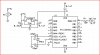
Your crystal needs two (typically) 22pF loading capacitors to work properly. Wire them like this (not a 16F84, but same idea):
There's the problem. Like I said previously, MCLR must be pulled high with a resistor. Your schematic shows it pulled low. When MCLR is held low the PIC is in RESET, and halted. No program runs with MCLR pulled low like that.
A pull up or pull down resistor is used to create a default value or state for a signal. Now you have MCLR wired to +5V. If you connect an ICSP it will not work because the signal is stuck at +5V. If you were to put a 10K or 20K resistor between MCLR and +5V then MCLR would be +5V when no other signal was present. But because of the resistor a signal from an ICSP connector could change the value to VPP or GND as needed.
A pull down works the same way but the default become GND.
Most often the an input will have a pullup or pulldown and one or more other signals that will be tristated (turned off or made an input) when not in use.
In case you didn't understand 3v0's pullup/pulldown explanation I found another on the interweb.
And, like 3v0 says, don't connect MCLR directly to VDD. Use a pullup resistor between the MCLR pin and VDD. 22K or 33K are good, but it isn't critical. Anything from 10K to 33K is fine.
This is really just personal choice, PIC's are designed for a direct MCLR connection if you wish, but obviously it prevents ICSP - if you don't use ICSP, then you don't need a resistor - if you do use ICSP, then you need a resistor and a diode.
This is really just personal choice, PIC's are designed for a direct MCLR connection if you wish, but obviously it prevents ICSP - if you don't use ICSP, then you don't need a resistor - if you do use ICSP, then you need a resistor and a diode.
I was under this assumption as well but it seems that later pics shouldn't have MCLR connected direct to Vdd.
From the 16F876A data sheet,
The behavior of the ESD protection on the MCLR pin
differs from previous devices of this family. Voltages
applied to the pin that exceed its specification can
result in both Resets and current consumption outside
of device specification during the Reset event. For this
reason, Microchip recommends that the MCLR pin no
longer be tied directly to VDD. The use of an RCR
network, as shown in Figure 14-5, is suggested.
This site uses cookies to help personalise content, tailor your experience and to keep you logged in if you register.
By continuing to use this site, you are consenting to our use of cookies.


")