Continue to Site

Welcome to our site!

Electro Tech is an online community (with over 170,000 members) who enjoy talking about and building electronic circuits, projects and gadgets. To participate you need to register. Registration is free. Click here to register now.

  • Welcome to our site! Electro Tech is an online community (with over 170,000 members) who enjoy talking about and building electronic circuits, projects and gadgets. To participate you need to register. Registration is free. Click here to register now.

CDI project

Status
Not open for further replies.

yusuf86

New Member
Hello everyone !
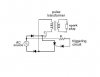
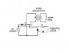
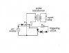
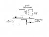
I'am just designing a Capacitive Discharge Ignition Project (Not to be used for a vehicle), I have tried to create a circuit diagram so just need to know whether it will work or not... and of course all your suggestions and reviews are welcomed !
PS : Please IGNORE any silly mistakes in the circuit coz I'm a newbie.
 

Attachments

  • C_D_I.JPG
    C_D_I.JPG
    14.4 KB · Views: 245
Last edited:
Not a useable circuit.

First, the goal should be to establish a current in the coil primary, and then suddenly turn off the switch. The collapsing coil current is what makes the spark. Your idea (I think) is to establish the current, and then let the SCR turn off due to the zero-crossing of the AC input, which has nothing to do with the coil current.

Second, you have wiring mistake such that the AC source is shorted by the SCR.
A capacitive discharge system does not use the inductance of the coil to generate the high voltage as a flyback circuit does. Instead it suddenly discharges a high voltage from a capacitor into the primary, with the coil acting as a transformer to step up the voltage. So the idea of his circuit is to charge the capacitor up to the peak of the AC voltage on each cycle and then discharge the cap with the SCR.

But your concern about the AC being shorted by the SCR would seem valid. If you triggered the SCR at the zero crossing or the negative cycle of the AC then the discharge would be complete and the SCR turned off before the AC current flow of the next cycle starts.
 
If its a line powered CD system you need here is the simplest version I have been able come up with. :)

Line voltage CD ignition coil Driver.jpg
 
Thank u both for your suggestions .. indeed the SCR is being shorted by the AC source so i have added a diode at the junction of SCR and AC source. Will this circuit work fine ?.. If NOT please suggest me ways by which i can make it work. I need to keep it SIMPLE yet working . Thanks a lot
 

Attachments

  • C_D_I(1).JPG
    C_D_I(1).JPG
    14.6 KB · Views: 261
Thank u both for your suggestions .. indeed the SCR is being shorted by the AC source so i have added a diode at the junction of SCR and AC source. Will this circuit work fine ?.. If NOT please suggest me ways by which i can make it work. I need to keep it SIMPLE yet working . Thanks a lot
The added diode is in the forward direction so it will do nothing to stop the current.

tcmtech's circuit adds a resistor in series with the transformer to limit the current, so that should work.
 
Just keep in mind that a high voltage only appears on the secondary when the current on the primary is switched off.
 
The added diode is in the forward direction so it will do nothing to stop the current.

tcmtech's circuit adds a resistor in series with the transformer to limit the current, so that should work.

tcmtech's circuit has R1 in series with the transformer, so if i add a resistance after the diode will this thing work ?
 

Attachments

  • C_D_I(2).JPG
    C_D_I(2).JPG
    14.7 KB · Views: 179
tcmtech's circuit has R1 in series with the transformer, so if i add a resistance after the diode will this thing work ?
That should work.
 
But the trigger point for the SCR is not well controlled and may trigger at too low a voltage. If you want it to trigger at the peak of the sine-wave you need to add a zener to get the desired trigger voltage in series with the SCR gate (zener anode toward the gate).
 
But the trigger point for the SCR is not well controlled and may trigger at too low a voltage. If you want it to trigger at the peak of the sine-wave you need to add a zener to get the desired trigger voltage in series with the SCR gate (zener anode toward the gate).

OK.. I've added a zener diode in series with the gate, with anode facing the gate, now can you please relate the values of these devices with each other. As I Don't know how many ohms resistor do i need to control the gate current, what diodes to use and what zener diode to use etc...
My requirements are :
Capacitor 2uF-5uF
Output voltage 5-6 KV
Keeping in mind the stored energy of the capacitor and the output voltage, Please tell me the suitable values of other components in the circuit.
 

Attachments

  • C_D_I(3).JPG
    C_D_I(3).JPG
    15.1 KB · Views: 173
So where is the problem with building it as I have shown it in the schematic? :confused:
 
So where is the problem with building it as I have shown it in the schematic? :confused:

Hi tcmtech !.. yeah i have gone thru the schematic which u have provided.. i have as few things to ask u..
1. what should be the value of R1 in ohms ? as i don't need an incandescent bulb in there
2. what is an X2 ? is it necessary to add X2 ? or can i replace it with a zener diode ?
3. Of what amperage must be D1 ? (eg. it should be 3X the running amps that is , 20 X 3= 60 A? )
4. of what amperage must be X1 ? (eg. its written it should be 20 amps or more) i guess 20 Amps is a hell lot of current
Please help me with these answers :)
thanks !
 
R1 sets the charge up time between pulses it can be anything from around 250 ohms to a mega ohm. Obviously the more resistance the longer the dead time between pulses.

D1 can be size to what ever input current your resistor allows through. If its a 250 ohm resistor then it would let .9 amps through at 230 volts so D1 would need to be rated for 1 amp or more.

X2 is a MOV similar device that has a specific break over voltage where it goes from non conducting to conducting at a specific point then resets once the input voltage drops far enough. As mentioned in the schematic mini neon bulbs also work well for this too.

X1 rating should be high enough to handle the discharge current that comes off of C1 through the coil. Depending on the coils resistance and the voltage that C1 gets charged up to before X1 fires that can be quite high if C1 has a very low ESR. Figure 20 amps is typically a good starting point to work with although you may get by with less too but it just depends on how hard you want to drive the circuit.
 
Last edited:
Status
Not open for further replies.

New Articles From Microcontroller Tips

Back
Top