Hi all
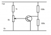
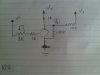
I'm "designing" the attached circuit. I'm measuring the voltage at point A from ground. If I have the pot turned up giving a total of 6K to the base, I measure about 22 mv. If I turn the pot down all the way, leaving about 1K into the base, I measure about 15mv.
The transistor is a regular NPN.
What I am trying to accomplish is a poor man's "voltage controlled resistor", specifcally the 100K across the Collector/Emitter junction of the transistor. I've attempted to create a voltage divider with the additional 100K resistor to V+, hence the reading at point A.
I'm not 100% sure what I should expect to measure at point A. Seeing the variable voltage indicates to me that its working in general but I was hoping for a second pair of eyes to double check my assumptions.
I got this idea from reading a synth schmatic over at:
http://satcom.tonnarelli.com/files/wp20/WP-20b.bmp
Cheers!
")