Electro Tech is an online community (with over 170,000 members) who enjoy talking about and building electronic circuits, projects and gadgets. To participate you need to register. Registration is free. Click here to register now.
Welcome to our site! Electro Tech is an online community (with over 170,000 members) who enjoy talking about and building electronic circuits, projects and gadgets. To participate you need to register. Registration is free. Click here to register now.
BMP is the worst possible format you could attempt to use, it's totally uncompressed (hence the large size) - it's too large to post.
Convert it to a more sensible format, then post it - if it's a diagram with very few colours (like a computer drawn circuit) try using GIF, if it's a scan or a photograph, use JPG instead. In any case, try both formats and see which is smallest.
Open the image in whichever image editing program you normally use, then choose "Save As" from the "File" list and, hopefully, you should find you can alter the image type before clicking on "Save".
Just change it to *.jpg or *.jpeg, however it shows it...
If this doesn't help, tell me what you use to view or edit images on your PC and we'll go from there.
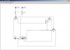
As Nigel said, your circuit is very confusing. The components are so spread out that you need to pan back and forth, up and down to cover the whole thing. Because it is not all in view at once it is difficult to make sense of it. If you closed them up a bit it would help. I cannot get a printout of the complete thing.
Also, there is a convention in circuit layouts that wherever possible the most +ve rail should be at the top and the most -ve one at the bottom. It is then possible to see the voltage potential gradient in the circuit.
Signal inputs should be shown at the left and outputs at the right. Then it's possible to see fairly quickly what the circuit is all about.
With your circuit it is not possible to see what is supposed to be going on without redrawing it.
would it be easier to forget my terrible diagram :?:
it want a simple circuit taht means i can use a 12V drill motor as the drive for an existing remote control car unit.
would it be easier to forget my terrible diagram :?:
it want a simple circuit taht means i can use a 12V drill motor as the drive for an existing remote control car unit.
Sounds like you need an h-bridge. i'll let someone more knowledgable tell you more about exactly what you're looking for. In the meantime, google search "h-bridge"
This site uses cookies to help personalise content, tailor your experience and to keep you logged in if you register.
By continuing to use this site, you are consenting to our use of cookies.

 i fianly got the diagram on