Continue to Site

Welcome to our site!

Electro Tech is an online community (with over 170,000 members) who enjoy talking about and building electronic circuits, projects and gadgets. To participate you need to register. Registration is free. Click here to register now.

  • Welcome to our site! Electro Tech is an online community (with over 170,000 members) who enjoy talking about and building electronic circuits, projects and gadgets. To participate you need to register. Registration is free. Click here to register now.

circuit question number one.

Wes76

New Member
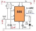
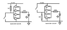
I made this circuit and it works as open circuit.(power applied, led comes on) I want to make it work with a remote off/on switch, that is closed (powered) in its resting state; when the switch is depressed, then the led would come on. (along with a buzzer added that I haven't shown in this photo. Parts are: 555, 1K resistor, 1MK resistor, 100n cap, 2 (or less) µf cap and 220 ohm resistor for the led. I used the schematic in the 2nd photo as a starting point. Any ideas will be appreciated. I don't even know if it's possible to use this arrangement to work like I imagine.
Monostable protoboard.jpg
 

Attachments

  • #2 Momostable - One Shot.jpg
    #2 Momostable - One Shot.jpg
    39.9 KB · Views: 24
Hi,
It would perhaps be easier to use a CD4049 Quad inverting buffer IC instead of the 555, in conjunction with a DC operated piezo-buzzer such as https://www.rapidonline.com/r-tech-350204-12v-pcb-piezo-sound-generator-3-20vdc-35-0204. The attached schematic shows the required connections. The buzzer has a built-in oscillator and only requires DC voltage to work. It consumes 15mA. The 4xganged inverters shown in the schematic will supply enough current for both the LED & buzzer. The schematic only shows the LED. To also connect the buzzer, connect its +ive terminal to the joined up outputs of the inverters and its -ve terminal to earth.

There are 6 inverters in the CD4049, and you can connect all 6 just as I have shown with 4 of the inverters (ie ganging up all 6 together)

EDIT: 08 Mar 2025. I had inciorrectly labelled the two schematics. I have now swapped over their labels and they are now correctly labelled
 

Attachments

  • Remote LED.jpg
    Remote LED.jpg
    73.4 KB · Views: 2
Last edited:

Latest threads

Back
Top