Continue to Site

Welcome to our site!

Electro Tech is an online community (with over 170,000 members) who enjoy talking about and building electronic circuits, projects and gadgets. To participate you need to register. Registration is free. Click here to register now.

  • Welcome to our site! Electro Tech is an online community (with over 170,000 members) who enjoy talking about and building electronic circuits, projects and gadgets. To participate you need to register. Registration is free. Click here to register now.

Controlling the resonance on a low pass filter

Status
Not open for further replies.

djstumerch

New Member
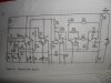
Hi everyone, I have breadboarded a low pass filter from the schematic I have attached. The cutoff works quite nice but the resonance seems to clip the LFO. I don't know how I could modify the schematic so I could control the resonance? Any help would be appreciated.

Thanks Stu
 

Attachments

  • SAM_0640.JPG
    SAM_0640.JPG
    809.7 KB · Views: 239
  • lowpass filter LFO.wav.zip
    5.2 MB · Views: 117
Last edited:
1. No schematic that I can see.
2. Low-pass filters don't resonate. They have a cutoff frequency (usually labeled f-sub-c in formulae); is that what you're talking about?
 
I used a lowpass second-order filter with its Q set higher than normal to make treble-boost on telephone boardroom high quality conferencing systems.
The resonance was at 3.5kHz and produced a peak in the frequency response of +10dB. It made the very muffled sound from ordinary telephone lines (3kHz was down -8db) sound crisp and clear.
 
Sorry I ve just uploaded the schematic now a long with an audio sample, there are a few alterations I would like to make, firstly I would like to separate the LFO from the circuit so sidechaining it is optional and also to have a pot controlling the cutoff frequency. As you can hear on the audio sample when the filter sweeps into the lower frequencies it often clips I had assumed this was because there was a set resonance which is why I was looking for a way to control it with a pot, any suggestions as to avoid this clipping sound would be much appreciated.

Thanks Stu
 
The real-time-analyser on my pc shows that the amplitude of the filter is increased at high frequencies. The amplitude of the filter is very low at low frequencies and is lower than the level of the background music, except when it is swept quickly at low frequencies when the output is much higher and causes popping.

I didn't hear the output of the filter clip at low frequencies but it popped when it swept quickly at low frequencies. The popping is probably caused by a DC offset voltage when the frequency reaches 0Hz. Simply prevent the frequency from going down to zero.

Maybe when you sweep quickly at low frequencies then the filter has nothing to filter?
 

Attachments

  • variable lowpass filter.PNG
    variable lowpass filter.PNG
    12.5 KB · Views: 148
Ok, thanks for your help, just tried putting a 1k resistor in series with the 100k pot to try and stop it reaching 0Hz but still experiencing the same problem. Also would you know where I could put a pot to control the cut off frequency rather than using the LFO? Finally I ve recently read that a lowpass filter can be converted into a high pass filter by 'transposing the resistor and the capacitor', this seems straight forward on the simple circuit shown in the book but not really sure how I would go about converting this circuit. Any answers are greatly appreciated. Thanks
 
I listened again to your audio sample. I don't hear the effect of the LFO sweeping of the lowpass filter frequency up and down but I do hear you sweeping the frequency a lot manually.
The 100k pot is supposed to vary the amount of sweep (not the lowpass filter frequency) that is provided by the LFO. The 2.2M pot is supposed to control the frequency of the LFO. So I think the LFO is not oscillating (maybe because C6 is a polarized electrolytic instead of a non-polarized film type) and that forces IC2 to simply be a variable DC voltage that manually adjusts the frequency of the lowpass filter with the 100k pot.

The datasheet of the LM13700 shows how to make it a highpass filter. I think then the source impedance to the input capacitor must be very low like the output of an opamp.
 
Status
Not open for further replies.

New Articles From Microcontroller Tips

Back
Top