Continue to Site

Welcome to our site!

Electro Tech is an online community (with over 170,000 members) who enjoy talking about and building electronic circuits, projects and gadgets. To participate you need to register. Registration is free. Click here to register now.

  • Welcome to our site! Electro Tech is an online community (with over 170,000 members) who enjoy talking about and building electronic circuits, projects and gadgets. To participate you need to register. Registration is free. Click here to register now.

Cut off voltage lithium battery?

Status
Not open for further replies.
While waiting for components to arrive I have an other idea that may be bad or can work. Would be fun trying :)

I have a buzzer for lithium batteries. You connect the balance cable and set cut off voltage with a small button (between 2.7-3.8v). It makes a loud sound if any of the cells gets below your adjustment. It sends 3v to the horn that beeps.

If its possible, can I remove the horn and replace it with a relay that cuts off load when it "beeps"? A problem is that it beeps one time when you connect it to battery and that beep will trigger relay. I was thinking that maybe with a timer skip that first beep or something.
And that relay cuts off both load and buzzer itself. Buzzer consumes 9ma.
Is this something that can be done? :)

( This is not a replacements or anything I will choose instead of your circuits that I trust more. Just curious to know if it is working)

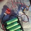
Buzzer looks like this:
image.jpeg

Timer circuit:
image.png
Like always, your answers are appreciated and exciting
 
While waiting for components to arrive I have an other idea that may be bad or can work. Would be fun trying :)

I have a buzzer for lithium batteries. You connect the balance cable and set cut off voltage with a small button (between 2.7-3.8v). It makes a loud sound if any of the cells gets below your adjustment. It sends 3v to the horn that beeps.

If its possible, can I remove the horn and replace it with a relay that cuts off load when it "beeps"? A problem is that it beeps one time when you connect it to battery and that beep will trigger relay. I was thinking that maybe with a timer skip that first beep or something.
And that relay cuts off both load and buzzer itself. Buzzer consumes 9ma.
Is this something that can be done? :)

( This is not a replacements or anything I will choose instead of your circuits that I trust more. Just curious to know if it is working)

Like always, your answers are appreciated and exciting

Hy Rorut,

Yes, that can be done.

Can you give a complete circuit of the detector battery voltage detector.

My initial feeling is that the 555 circuit can be modified to stay in the fault state and the output of the 555 could be used to open the contacts of a relay. But it does depend upon the characteristics of the relay coil.

Nice of you to say you appreciate answers. In response, I like good questions.

spec

Hi Spec :)
Did not find any datasheet but here is a picture from the circuit.
image.jpeg
I think I have a relay like this.
https://www.electrokit.com/rela-srd-1pol-vaxlande-5v.42004
Thank you very much
 
Hi Spec :)
Did not find any datasheet but here is a picture from the circuit.
View attachment 99561
I think I have a relay like this.
https://www.electrokit.com/rela-srd-1pol-vaxlande-5v.42004
Thank you very much

The relay should be OK. The 555 can drive 200mA and the relay coil is around 70mA.

This is how a possible solution looks at the moment off the top of my head. Connect the relay to the output of the 555 and modify the 555 circuit slightly. Would you be able to do that?
spec
 
The relay should be OK. The 555 can drive 200mA and the relay coil is around 70mA.

This is how a possible solution looks at the moment off the top of my head. Connect the relay to the output of the 555 and modify the 555 circuit slightly. Would you be able to do that?
spec
I think so. Thank you for verifying that the idea possibly works
 
I think so. Thank you for verifying that the idea possibly works
No sweat Rorut,

If you need my, or any other ETO members help, we would really need a bit more information to do a decent job.

Are you getting the electronics bug- if so, go and see your doctor as soon as possible.:D

spec
 
Thanks I will keep that in mind. Didn't find any more information about this and sorry if I was not clear enough.
Well, the bug really got me but frustrated I dont understand everything. So much to learn. Sad I didnt got the bug earlier :)
 
Thanks I will keep that in mind. Didn't find any more information about this and sorry if I was not clear enough.
Well, the bug really got me but frustrated I dont understand everything. So much to learn. Sad I didnt got the bug earlier :)
Ah, I thought so.

To get the basics of electronics is very easy. Electronics is heavily based on the application of maths so, to get started, you need arithmetic and fundamental algebra. All you need to do then is to visualize electrons flowing through a conductor (current), the thing that forces them to flow (voltage), and the thing trying to stop the electrons (resistance). It is very important to fully understand one stage and only then move on to the next stage. That way you are building on firm foundations.

The relationship between current, voltage, and resistance is defined quite simply by Ohms law: I=V/R

Then learn Kirchoff's first and second laws, which are also dead simple (obvious really) and you will have a firm grounding in the subject. I could not come to terms with Kirchoff's laws partly because of the frighting name but also because they are so simple. I thought I must have gone wrong because they seemed so obvious and basic- but no, that is what they are.

Next capacitors- conceptually awkward but not difficult

Inductors- as capacitors, but a bit more tricky.

Transformer- simple

The next move would be to learn the two fundamental functions of silicon diodes.

The next move would be to learn the two fundamental functions of bipolar junction transistors.

And then learn the one fundamental function of MOSFETs.

After that you have all the tools to design/understand some pretty sophisticated analog circuits.

The next move would be to learn the one basic function of an operational amplifier (comparators are pretty much the same)

And then you could design/understand some very sophisticated analog circuits.

The above would be the foundations of analog design.

Then there are the fundamentals of the digital field which, in principle, are not difficult either.

Things do get really heavy in advanced analog and digital designs though, but you needn't worry about that. As in most subjects, you never stop learning about electronics, and it is vital to learn by your mistakes- I do everyday.

If anyone is getting into electronics, or any field for that matter, getting a good book on the subject is essential.

It is all very nice for me to say all this after years of experience, and of course it is a gross oversimplification, but in principle, it is correct. I have tutored many people at work who have been struggling, even after learning the theory at university or tech college (by the way this is no indictment of academia- in fact most of the ex-grads were amazingly talented both in theory and practical). But after getting just a few basic practical principles under their belts, they have progressed well. I had the same experience when I was starting out in electronics; the advice came from other engineers, including grads, in our department. I seem to have a different way of learning to most people; I struggle learning the advanced stuff until I fully understand the basic function. Some other ETO members have said the same thing.

To take an example, many students knew how to do all the calculations for an opamp: gain, offset, frequency stability etc, but, in spite of learning all the difficult stuff, they didn't know how to apply an opamp (apart from in the classic configurations that is) in a practical circuit, because they didn't appreciate the one fundamental characteristic of an opamp: it cannot abide its two inputs being even minutely different and will do all it can, by altering its output, to achieve this balance. It does not matter where the opamp is in the circuit, this fundamental axiom applies.

As you may have guessed, learning about electronics is a hobby horse- it is the waste of talent for someone who is struggling that gets me.

Lecture over.

spec
 
Last edited:
Hi everyone....if u have four Panasonic NCR3400 batteries, but I cant find that part number. Did you mean NCR18650B?Actyually the critical areas to get right in a cut off circuit (COC) is battery rebound, and this depends on the load (last) and the battery characteristics.Basically, without the correct window (hysteresis), the COC will oscillate: on load the battery voltage drops to 3.5V and the COC activates and removes the load. This causes the battery voltage to rise (rebound) and the COC reconnects the load and so the cycle continues.

prototype turnkey assembly
 
Last edited:
Ah, I thought so.

To get the basics of electronics is very easy. Electronics is heavily based on the application of maths so, to get started, you need arithmetic and fundamental algebra. All you need to do then is to visualize electrons flowing through a conductor (current), the thing that forces them to flow (voltage), and the thing trying to stop the electrons (resistance). It is very important to fully understand one stage and only then move on to the next stage. That way you are building on firm foundations.

The relationship between current, voltage, and resistance is defined quite simply by Ohms law: I=V/R

Then learn Kirchoff's first and second laws, which are also dead simple (obvious really) and you will have a firm grounding in the subject. I could not come to terms with Kirchoff's laws partly because of the frighting name but also because they are so simple. I thought I must have gone wrong because they seemed so obvious and basic- but no, that is what they are.

Next capacitors- conceptually awkward but not difficult

Inductors- as capacitors, but a bit more tricky.

Transformer- simple

The next move would be to learn the two fundamental functions of silicon diodes.

The next move would be to learn the two fundamental functions of bipolar junction transistors.

And then learn the one fundamental function of MOSFETs.

After that you have all the tools to design/understand some pretty sophisticated analog circuits.

The next move would be to learn the one basic function of an operational amplifier (comparators are pretty much the same)

And then you could design/understand some very sophisticated analog circuits.

The above would be the foundations of analog design.

Then there are the fundamentals of the digital field which, in principle, are not difficult either.

Things do get really heavy in advanced analog and digital designs though, but you needn't worry about that. As in most subjects, you never stop learning about electronics, and it is vital to learn by your mistakes- I do everyday.

If anyone is getting into electronics, or any field for that matter, getting a good book on the subject is essential.

It is all very nice for me to say all this after years of experience, and of course it is a gross oversimplification, but in principle, it is correct. I have tutored many people at work who have been struggling, even after learning the theory at university or tech college (by the way this is no indictment of academia- in fact most of the ex-grads were amazingly talented both in theory and practical). But after getting just a few basic practical principles under their belts, they have progressed well. I had the same experience when I was starting out in electronics; the advice came from other engineers, including grads, in our department. I seem to have a different way of learning to most people; I struggle learning the advanced stuff until I fully understand the basic function. Some other ETO members have said the same thing.

To take an example, many students knew how to do all the calculations for an opamp: gain, offset, frequency stability etc, but, in spite of learning all the difficult stuff, they didn't know how to apply an opamp (apart from in the classic configurations that is) in a practical circuit, because they didn't appreciate the one fundamental characteristic of an opamp: it cannot abide its two inputs being even minutely different and will do all it can, by altering its output, to achieve this balance. It does not matter where the opamp is in the circuit, this fundamental axiom applies.

As you may have guessed, learning about electronics is a hobby horse- it is the waste of talent for someone who is struggling that gets me.

Lecture over.

spec
Thank you very much for such valueable information. I will definitely try and learn more in the order you describe. It is often difficult to know where to start. I think I need a good book to begin with. There is so many details :) I know some basics already but when it comes to figure out a solution for a need there seem to be so many ways it can be done. Diffucult to know which way to go for the best solution and there is always so many new things I didnt know from before. But I'm not the person that gives up. This is actually a way for me to relax after work. My wife thinks I'm crazy
Components arrived today and I will try to complete one of the circuits after work tomorrow. I can not wait :)

(need to wait a couple of days. Need to take care of my son who became ill)
 
Last edited:
Hi everyone....if u have four Panasonic NCR3400 batteries, but I cant find that part number. Did you mean NCR18650B?Actyually the critical areas to get right in a cut off circuit (COC) is battery rebound, and this depends on the load (last) and the battery characteristics.Basically, without the correct window (hysteresis), the COC will oscillate: on load the battery voltage drops to 3.5V and the COC activates and removes the load. This causes the battery voltage to rise (rebound) and the COC reconnects the load and so the cycle continues.
Hi and thank you for your feedback DalDames. Yes NCR18650B. I think that is covered in the circuits made for me by the kind people here in the thread. I appreciate your input
 
The relay should be OK. The 555 can drive 200mA and the relay coil is around 70mA.

This is how a possible solution looks at the moment off the top of my head. Connect the relay to the output of the 555 and modify the 555 circuit slightly. Would you be able to do that?
spec

Hi again,
Today I tried to put together the 555 circuit and it seems to work. If I connect 3.3v from a power supply and have a LED on output on the 555 it waits until capacitor gets loaded and then lights constantly.

Problem is when i instead connect battery pack to buzzer and buzzer to 555 circuit . When battery voltage gets low it sends between 3.73-3.8v pulsating to horn. I unsoldered the little horn and connected the buzzer output to my 555 circuit and LED now is lighting very dim and flashes. I tried to put a capacitor (1000uf,25v) between buzzer output and 555 input but voltage doubles and LED is more bright but still flashes but with much shorter interval. (only putting a capacitor on buzzer output and measuring voltage not connected to 555 it looks stable 7.6v)
What can I do to stabilize the output voltage from buzzer to the 555 circuit?
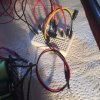
IMG_0163.JPG IMG_0164.JPGimage (1).png

555 circuit contains:
LMC555
100uf, 25V
47K

I don´t want to give up on this before I continue to build rest of the circuits :)
 
Last edited:
Your 555 circuit is wrong and will not do anything. You should look at the circuits in the datasheet of the LM555 and LMC555.
You show four Lithium battery cells powering an LMC555. The four cells will produce 16.8V when fully charged but the datasheet for the LMC555 shows an absolute maximum supply of only 15V so maybe your LMC555 is destroyed.
 

Attachments

  • 555 circuit.png
    555 circuit.png
    63.8 KB · Views: 167
Your 555 circuit is wrong and will not do anything. You should look at the circuits in the datasheet of the LM555 and LMC555.
You show four Lithium battery cells powering an LMC555. The four cells will produce 16.8V when fully charged but the datasheet for the LMC555 shows an absolute maximum supply of only 15V so maybe your LMC555 is destroyed.
I show four lithium cells connected to a buzzer.
The buzzer alarms when any of the cells gets under adjusted lowest voltage. I removed the buzzer horn which is powered by ~3v from the buzzer. Im using the 555 circuit to avoid a first beep made by the buzzer on power on. It is not sending 16.8v to the circuit. Sorry if Iwas not clear enough. Problem is its not constant 3v . It is pulsating and if I connect a capacitor to the cables from the buzzer i get double voltage
 
Maybe the buzzer horn is not a DC buzzer, it might be an AC transducer (speaker) instead. Then maybe you measured the average 3VDC of an AC signal that drives the transducer. If the AC signal goes from 0V to about 7.6V peak to peak then a capacitor on it might filter the signal to produce 7.6VDC.

I see that your LMC555 circuit output goes low immediately when power is applied then goes high after a delay to prevent the power-up first beep.

You said that you connected the buzzer output to the 555 circuit but your schematic does not show what the buzzer output connects to on the 555 circuit.
 
Thank you for your answer!
I didnt think of that. How do I know if its AC? Possible to see it somehow? Is it also why LED is flashing? If I want to convert it to DC is a bridge rectifier the way to go or any other simple solution.

I connected buzzer "horn output" to pin-8 and ground on 555. Was that correct?

(Lmc555 could go lower than 5v minimum. Thats why I choosed that one. Thought they had the same configuration)
 
Last edited:
My oscilloscope shows AC and DC much better than a meter that is very slow. I have a little battery powered amplifier with built-in speaker that plays an audio sound if there is audio AC.
An LM555 or LMC555 does not have a terminal called "Vin" but maybe you fed the buzzer output to the power supply input parts of your schematic shown as +5V?
Yes sorry, pin-8 and pin-1.

Is a bridge rectifier and a capacitor enough to fix DC?

Or maybe go for more than 1000uf
 
Last edited:
We do not know what the buzzer output is doing. AC? DC? Pulsing? How much output current?

The LMC555 is not powerful enough to turn on your 70 ohms relay coil plus the LED because its Cmos parts depend on a high supply voltage to produce high current. Also its output high current is less than its output low current.
The datasheet for the LMC555 shows its output voltage dropping a lot when its output high current is only 0.25mA with a 1.5V supply and dropping noticeably when its output high current is 2mA when its supply is 5V. Your 70 ohm relay coil draws 3V/70 ohms= 43mA.
The datasheet for the TLC555 shows even less output high current when its supply is only 3V.
The datasheet of the ICM7555 also shows very low output high current when its supply is only 3V.
Therefore the LMC555 cannot drive the relay plus the LED in your circuit.

An ordinary LM555 has a higher output high current but still not enough and its minimum supply is 4.5V.

Without the LMC555 does the buzzer output provide enough power to activate the relay?

I think the buzzer output can turn on a transistor or darlington transistor that can activate the relay and LED when they are powered from a higher supply voltage. The transistor have a delayed turn on.
led is just for testing circuit. Will not use it together with relay. Will do some more tests later. Thx audioguru!
 
Status
Not open for further replies.
Back
Top