Continue to Site

Welcome to our site!

Electro Tech is an online community (with over 170,000 members) who enjoy talking about and building electronic circuits, projects and gadgets. To participate you need to register. Registration is free. Click here to register now.

  • Welcome to our site! Electro Tech is an online community (with over 170,000 members) who enjoy talking about and building electronic circuits, projects and gadgets. To participate you need to register. Registration is free. Click here to register now.

Electret mic and phone for heart and lung sound for telemedicine

Status
Not open for further replies.
My circuit has the needed lowpass filter that can have switched frequencies if you want. An adjustable pot can be used as a gain control. It works fine.
Has anybody tried using a piezo transducer feeding a Jfet? Its horrible frequency response will seriously mess up lung sounds.
 
Sorry doldett. I don't have the expertise to come up with a suitable circuit for your endevour and AG seems entirely consumed with defending his 17 y/o design for a circuit that is unsuitable for your purpose; despite that noone is attacking it, beyond agreeing with him that it is unsuitable for your purpose.

Maybe that was his peak and he cannot -- or cannot be bothered to -- design anything new.
That's ok Buk. I have not done more tests as I am waiting for female trrs socket from china so that more future experiments could be performed without concerns on unshielded audio cable. I will also test what voltage does cause the phone and ipad to clip. Again need to wait for trrs socket on the perfboard to be able to probe it. Please bear with me a little longer.

I am gonna try to make AG's circuit to work on this project as the gain of the circuit can be adjusted.
 
The first opamp of the mic preamp is important because the input of the Sallen-Key lowpass filter needs its very low impedance output. Also, the gain of the filter must not be adjusted but the first opamp can have adjustable gain.
For the output of the mic preamp circuit you can use an ordinary shielded audio cable (many come with RCA plugs) and a TRRS plug soldered on to the phone end of it. Then you do not need a TRRS socket.
 
The 3M and Welch Allyn electronic stethoscope user manuals have no technical details. The Welsh Allyn says "Patented Directional Pressure Sensor" but does not say Piezo.
The 3M sales sheet says it records up to 12 tracks and communicates with Bluetooth.

A review for a Piezo contact mic says it needs a preamp with an "Ultra High input Impedance" and says 10M ohms. It says that without the very high impedance load it produces no low frequencies and sounds tinny. A Jfet has an ultra high input impedance and a heartbeat is very low frequency.
 
Sorry guys. I have been a while since my last update. TRRS female socket received. Done some experiments and would like to update.

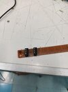
Here is trrs femal socket on the perfboard for phone input clipping test. Two jumper wires are for probing purpose.
IMG_20210825_124005.jpg
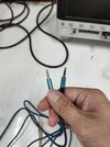
Male-to-mele trrs cable for connecting to phone.
IMG_20210825_124027.jpg
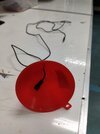
DIY Steth head with funnel and lavalier mic.
IMG_20210727_145937.jpg
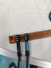
Connected according to this diagram.
diagram.png

IMG_20210825_124057.jpg

When speaking directly to the mic and recording the voice, recorded sound was clear and waveform had no clipping.
test if there is clipping.png

Since peak-to-peak signal of 280 mV does not clip the phone input, the output signal of the preamp circuit should be at this level as well. I then try to capture the voltage level of heartbeat signal and found that it is 40 mVpp.


In order to not exceed 280 mV, the gain of preamp circuit has to be less than 7. As the second stage has 1.6 gain, the first stage needs to be less than 4.38. I will need to adjust 1M pot to 158k if my calculation is right.

Here is recording and its spectrum. I think high intensity at low frequency corresponds well with the heartbeat.
sound spectrum.png


Although all audio cables are used in the test setup, the high pitch noise is still there. I am wondering if it is because of the use of perbboard or the exposed metal contact, which is mic signal, of trrs male on the phone like in the photo below. On the ipad, the exposed contact is worse.
img_0605-jpg.133360
 

Attachments

  • IMG_0605.JPG
    4.4 MB · Views: 615
Last edited:
  • Like
Reactions: Buk
An electret mic produces only 28mV p-p (10mV RMS) when talking to it at a conversation level at 10cm (4 inches) from your mouth. Your level is 10 times more so you must be screaming. My original preamp produced a line level output, not a mic level which is why it had a high max gain.
 
An electret mic produces only 28mV p-p (10mV RMS) when talking to it at a conversation level at 10cm (4 inches) from your mouth. Your level is 10 times more so you must be screaming. My original preamp produced a line level output, not a mic level which is why it had a high max gain.
Yes, I was screaming since I try to see whether the signal level could reach the clipping point.
 
An electret mic produces only 28mV p-p (10mV RMS) when talking to it at a conversation level at 10cm (4 inches) from your mouth. Your level is 10 times more so you must be screaming. My original preamp produced a line level output, not a mic level which is why it had a high max gain.
Hm.

According to the android specs, 3.5 mm Headset Jack: Device Specification, Audio(mic) in is required; Headset insertion detection is required; a Mic bias voltage of 1.8V - 2.9V with Maximum output voltage drive >= 150mV on 32 ohm is required.

And the Reference headset test circuit looks like this:
1629896883122.png


The Iphone/Ipad specifications are similar.

The electret mic in headsets are expected to draw their drive voltage/current from the DC bias voltage provided on the jack. And the input circuitry is designed to respond to that level of input. and there are very specific requirements for how they respond:

5.4. Audio Recording​

While some of the requirements outlined in this section are listed as SHOULD since Android 4.3, the Compatibility Definition for future versions are planned to change these to MUST. Existing and new Android devices are STRONGLY RECOMMENDED to meet these requirements that are listed as SHOULD, or they will not be able to attain Android compatibility when upgraded to the future version.


5.4.1. Raw Audio Capture and Microphone Information​

If device implementations declare android.hardware.microphone, they:


  • [C-1-1] MUST allow capture of raw audio content with the following characteristics:
    • Format: Linear PCM, 16-bit
    • Sampling rates: 8000, 11025, 16000, 44100, 48000 Hz
    • Channels: Mono
  • SHOULD allow capture of raw audio content with the following characteristics:
    • Format: Linear PCM, 16-bit and 24-bit
    • Sampling rates: 8000, 11025, 16000, 22050, 24000, 32000, 44100, 48000 Hz
    • Channels: As many channels as the number of microphones on the device
  • [C-1-2] MUST capture at above sample rates without up-sampling.
  • [C-1-3] MUST include an appropriate anti-aliasing filter when the sample rates given above are captured with down-sampling.
  • SHOULD allow AM radio and DVD quality capture of raw audio content, which means the following characteristics:
  • [C-2-1] MUST capture without up-sampling at any ratio higher than 16000:22050 or 44100:48000.
  • [C-2-2] MUST include an appropriate anti-aliasing filter for any up-sampling or down-sampling.

5.4.2. Capture for Voice Recognition​

If device implementations declare android.hardware.microphone, they:


  • [C-1-1] MUST capture android.media.MediaRecorder.AudioSource.VOICE_RECOGNITION audio source at one of the sampling rates, 44100 and 48000.
  • [C-1-2] MUST, by default, disable any noise reduction audio processing when recording an audio stream from the AudioSource.VOICE_RECOGNITION audio source.
  • [C-1-3] MUST, by default, disable any automatic gain control when recording an audio stream from the AudioSource.VOICE_RECOGNITION audio source.
  • SHOULD record the voice recognition audio stream with approximately flat amplitude versus frequency characteristics: specifically, ±3 dB, from 100 Hz to 4000 Hz.
  • SHOULD record the voice recognition audio stream with input sensitivity set such that a 90 dB sound power level (SPL) source at 1000 Hz yields RMS of 2500 for 16-bit samples.
  • SHOULD record the voice recognition audio stream so that the PCM amplitude levels linearly track input SPL changes over at least a 30 dB range from -18 dB to +12 dB re 90 dB SPL at the microphone.
  • SHOULD record the voice recognition audio stream with total harmonic distortion (THD) less than 1% for 1 kHz at 90 dB SPL input level at the microphone.

If device implementations declare android.hardware.microphone and noise suppression (reduction) technologies tuned for speech recognition, they:


  • [C-2-1] MUST allow this audio effect to be controllable with the android.media.audiofx.NoiseSuppressor API.
  • [C-2-2] MUST uniquely identify each noise suppression technology implementation via the AudioEffect.Descriptor.uuid field.
My point being that driving them with a signal amplified by a 12Vdc amp will screw things up. Including possible hadware damage.
 
A cell phone usually uses a headset mic that has its electret mic (or Mems mic) much closer to your mouth (1-2cm) than a lavalier or handheld mic (10cm) then its output signal will be a much higher level.

All 828 electret mics spec'd on Digikey datasheets show that their output impedance is 2.2k ohms and draw 0.5mA DC max, then powering them with a 2.2k resistor cuts their signal level in half. The current of 0.5mA in the 2.2k resistor powering the mic from 2.2V drops the DC voltage at the mic to only 1.1V when many electret mics do not work or have "sensitivity reduction".

I did not know that cell phone headsets have 4 buttons which control functions with low value resistors parallel to the mic.

The test condition EN50332-2 of 150mV maximum drive on a 32 ohms headphone is to avoid hearing damage, the 150mV is not from a microphone.

I agree that the opamp circuit in this thread should have an output attenuator so that the maximum signal level is not higher than a headset mic (2.2Vp-p).
 
I did not know that cell phone headsets have 4 buttons which control functions with low value resistors parallel to the mic.
It used to be very common with wired headsets - the earphone cable typically has a control unit inline with answer/hang up and volume buttons, plus the mic included so it hangs near your mouth or on your chest, lavalier style.
eg. this general type of thing:

wired_headset.jpeg
 
the 150mV is not from a microphone.
No, the 1.8V-2.9V @ ~<150mA is the DC bias voltage supplied by the phone that is intended to be used to drive the microphone. The 3 android phones I have available to meprovide 2.77V, 2.67V, and 2.9V

Here's one of them. (The red plug is right speaker output; but the same voltage appears on the green/yellow left speaker and the white mic in plugs)
1629925277844.png


An electret -- regardless of whether it is a stand-alone capsule, the one in a lapel mic, or the one in a headset -- can be driven directly from the trs connector without batteries using a simple circuit like this:
1629921517730.png

The same thing can be done with a trrs connector, with the power taken from either of the stero output connections.

I'm not saying that this is adequate for this stethoscope application as is, but it is easy to see that an amplifier that is also driven from this could be more than enough.
1629922758214.png


I don't have an iDevice to demonstrate with, but the same is true for them. Even my old feature phone provides 1.9V.
 
Last edited:
I did not know that cell phone headsets have 4 buttons which control functions with low value resistors parallel to the mic.
They have to have 1; can have upto 4; and android phones must support 4. The resistor values are flexible as they must be adapted to the resistance presented by the rest of the headset. It is the total resistance detected by the phone that allows it to enable support for 1 .. 4 buttons.
 
I agree that the opamp circuit in this thread should have an output attenuator so that the maximum signal level is not higher than a headset mic (2.2Vp-p).
Given the phone will provide 2.xV, what is the benefit of using a 9V or 12V amplifier and then attenuating its output to match the phones input stages?
 
There are 155 posts in this thread. Has anybody connected an electret mic to a cell phone to see if heartbeats are sent to a phone at the other end of a phone call or are recorded without a preamp or a lowpass filter?
If a preamp or sharp lowpass filter are needed then there are few if any low noise audio opamps that work with a voltage less than a run down (5V) 9V battery.
 
Has anybody connected an electret mic to a cell phone to see if heartbeats ... are recorded without a preamp or a lowpass filter?
Yes. I stuck the mic of my passive headset down my shirt, pressed it against my chest and with some shifting around, I got a very faint, but recognisible heartbeat. Absolutely swamped by noise of course. (The phone call bit is irrelevant.)

If a preamp or sharp lowpass filter are needed then there are few if any low noise audio opamps that work with a voltage less than a run down (5V) 9V battery.
Does it have to be (one or more) opamps? Can't you make some pretty good low-noise, low-gain amplifiers using j-fet(s)? (Isn't that why they are used internally to the electret capsules?)
 
There are 155 posts in this thread. Has anybody connected an electret mic to a cell phone to see if heartbeats are sent to a phone at the other end of a phone call or are recorded without a preamp or a lowpass filter?
If a preamp or sharp lowpass filter are needed then there are few if any low noise audio opamps that work with a voltage less than a run down (5V) 9V battery.
I did in my first post using WIFI for video call and also recently recording in the post #147.

You can listen to the recording here. The heartbeat was distinguishable corresponding well with its spectrum. Of course, high pitch noise almost swamp it. Don't know where the high frequency noise is coming from as all cables are all shielded.

sound spectrum.png
 
Last edited:
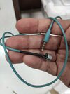
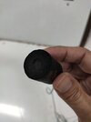
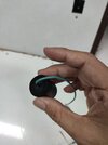
I had finished soldering electret mic to shielded audio cable and put it in heat insulation. At the other end, rubber feet is inserted to prevent the air coming in. Thinking of using hot glue on rubber as well to be sure it is airtight.

IMG_20210825_160341.jpgIMG_20210825_160745.jpgIMG_20210825_160801.jpgIMG_20210825_160804.jpg

DIY steth head with new hard plastic.
IMG_20210825_162259.jpg
 
  • Like
Reactions: Buk
The Jfet inside an electret mic is an impedance converter with an input resistor to ground that is 1G ohms. Operating at about 0.4mA (0.5mA max) and with a low value drain resistor is voltage gain is not high. Its output level is about the same as a dynamic mic (coil and magnet). A preamp is still needed.

"Learning about electronics" says some wrong things about electret mics:
 

Attachments

  • electret mic.png
    electret mic.png
    96.4 KB · Views: 261
Status
Not open for further replies.

New Articles From Microcontroller Tips

Back
Top