The LA100 is a transducer - it gives a small signal proportional to the main cable current, eg. 0-10V or 0-10mA for 0-100A or whatever. That needs feeding back to the PWM system for power control, and safety shutdown.
The existing controller should have a current sensor of some sort, either hall effect or often is smaller motor controllers just a low value resistor (even a piece of heavy wire). The output from that should be replaced by the LA100 output, adapted appropriately.
Proper motor speed controllers are complex things; you cannot just have a simple on/off control on something that size.
A stationary DC motor is almost a short circuit and if you "direct" start it with a switch, whether mechanical or electronic, it will try to take 5 - 10 times more than its rated current - so probably between 400 - 800 amps in your case.
Things tend to fail or explode rather rapidly like that, and you can be sure the batteries would be damaged!
What batteries are you intending to use, by the way?
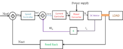
The power must be applied gradually to control the current & torque, using very short pulses, which because of the motor inductance never last long enough for the current to rise to a dangerous level. The current feedback part (the LA100) allows the PWM controller to monitor how much current the motor actually takes and modulate that according to the setpoint signal (throttle) and safe limits.
This is a basic block diagram of a motor speed controller; in older or simpler systems they may all be built with discrete components, opamps etc., or with newer ones the sensing parts feed in to a microcontroller and all the calculations are done in that, with it giving out a PWM signal to the motor power drivers.


