Continue to Site

Welcome to our site!

Electro Tech is an online community (with over 170,000 members) who enjoy talking about and building electronic circuits, projects and gadgets. To participate you need to register. Registration is free. Click here to register now.

  • Welcome to our site! Electro Tech is an online community (with over 170,000 members) who enjoy talking about and building electronic circuits, projects and gadgets. To participate you need to register. Registration is free. Click here to register now.

eq lizer circuit

Status
Not open for further replies.

MrDEB

Well-Known Member
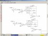
I plan on eliminating the diode going to ground from the + input of op amps. Maybe just ground the + inputs?? but it appears the + is kept high?
adding a transistor to the outputs of the lm3916 to sink more current and keep the leds all same brightness?
This is the basic circuit posted on ELECTRO TECH
Orginally was going to use the circuit as a 10 band eq but adding pots and concern about audio quality?
just going to do a TILT circuit and connect in parrell with this circuit.
any other suggestions?
 

Attachments

  • Capturesch.jpg
    Capturesch.jpg
    149.3 KB · Views: 338
oups wrong circuit diagram

here is the correct circuit
 

Attachments

  • abrivated circuit.GIF
    abrivated circuit.GIF
    67.3 KB · Views: 272
I can't remember the original Oriental circuit. I wish your project stayed in one thread.

The diode biases the input of the opamp at about 0.6V so that the collector of the switching transistor is at 0V without a signal. But the emitter has another diode so maybe the input of the opamp should have two diodes in series, then the input to the LM3916 will be 0V when the signal is zero.

The input of the LM391x needs a 1M resistor to ground or its input current will cause it to float high.

The max output current of the LM391x is about 30mA. The circuit multiplexes the columns so each LED will have an average current of 3mA max which is very dim. Of course the outputs of the LM3916 need a transistor to boost the current.

The switching of the transistors at the ouputs of the filter ICs might cause a buzz in the audio. Try it to see (hear).
 
I think this is the original Oriental circuit?
I just copied from my bookmarks.
Maybe adding transistors to the 3916 outputs and adding 750 ohm resistors to the leds as this seems to be enought brightness and only draw 5 ma per led on 12v(need to recheck)using smd leds.
as for sound I plan on not using the audio output from the display circuit as noise would be a problem.
going to run circuit in parrell w/ a TILT circuit.
 
If the LEDs are 2.0V red ones and the supply is 12.0V then the driving transistors will have a saturation loss of 0.2V then the 750 ohm current-limiting resistors get 9. 8V. The current calculates to be 13mA. The LEDs are multiplexed so each lights for only 1/10th the total time so will look light a current of only 1.3mA. Very dim. The LM3916 can have output currents higher but it will get hot since the supply voltage is so high.
 
led calculator/transistor

In the Oriential circuit he has no transistors on the 3916 but yes I think it needs them to allow adquete brightness.
any suggestions. I am perplexed when it comes to calculating transistor saturation, etc. Using the led calculator
at 12v, 2.0 forward voltage, 20ma max I see a 560 ohm resistor?
just need direction on transistor usage.
As for the noise - not going to use the audio from display. Planning on a TILT circuit in parelle with display.
In addition to the 10 x 10 matrix displays (2) I am hoping to put leds behind the knobs using clear plastic rod for knobs.
could look really cool. The entire knob lights up no just a halo effect around the knob.
At present, using the Oriental circuit but going stereo w/2- 10x10 displays, a stereo TILT circuit all on one 2 sided board. Displays on seperate board.
Using expresspcb for layout
 
I have a Sound Level Indicator project which is an LM3915 driving 10 pairs of LEDs in series at 25mA each and they are normal sized but very bright ones.

You are using tiny little LEDs and I don't know their max continuous current and max pulsed current. I also don't know their brightness and how bright you want them to be.

With a 12.0V supply, a 2.0V LED and transistor saturation voltages of 0.2V then your 560 ohm resistor (and the LED that it feeds) has a current of 9.8V/560= 17.5mA.
After multiplexing the LEDs will be very dim.
 
the led specs?

the yellow leds which I think are the weakest as we poped one with a 6v battery (none of the other leds poped.
they are OSRAM LY-T686
they show a pulsed current? as well as max surge current of .2A
maybe with the multiplxing we should just leave out the resistors but have a pot to adjust the led intensity? as noted in the lm3916 data sheet?
 
The LEDs have a typical forward voltage of about 2.0V. The max continuous current is only 30mA. A 6V battery will cause a current of a few amps and will bust them.

The LM3916 has a max output current of only about 25mA which is fine for driving LEDs continuously but is much too low for these multiplexed LEDs.

You need to use transistors at each end of the LEDs and use current-limiting resistors then you cannot adjust their brightness with a pot on the LM3916 because the transistors are just on-off switches.

I think you should use a current in the LEDs of about 150mA and have the multiplexing operate at 1kHz then the on-time of each LED is 0.1ms which is much less than the max for high current pulses of 10ms.
 
It is not an equalizer circuit anymore. Now it is an octave-band level display circuit. There is a VU meter for each octave band.

When he gets this working then he will make a separate octave-band equalizer circuit.
 
Well, the circuit I have mentioned is the same thing, Its'nt? measures each octave with the LM3915, and then multiplexates the data.
 
lm3916 multiplexing solution?

If I connect a transistor to the lm3916 outputs to increase the sink capbilities, have a 750 ohm resistor in series and 9 volt power supply for trsansistor switching, the leds should only draw 12ma each. being they are in parrell the current draw should be all equal so the leds woon't be dim?
biasing the transistor connected to the lm3916 outputs?
did a TINA simulation and a 500 ohm resistor ??
the rest f the circuit is the Oriental circuit.
not sure if this is correct approach?
 

Attachments

  • lm3916 output.GIF
    lm3916 output.GIF
    59.4 KB · Views: 274
The LEDs are not driven in parallel.
The multiplexing by the CD4017 drives LEDs in one column (frequency band) at a time. Since you have 10 columns then each LED that is turned on is on for only 1/10th of the total time so it appears 1/10th as bright as one that is turned on continuously with the same current.

That is why I said to use 150mA in the LEDs and transistors so that they will appear as bright as an LED with 15mA continuously. Their max allowed current is 200mA for 5ms.

The 10k base resistor for the pullup transistor has a value much too high for the transistor to conduct 150mA. The output current from the CD4069 is barely enough to drive a 560 ohm resistor for 10mA base current from a 12V supply. If the supply is only 9V then the CD4069 won't provide enough base current for the transistor. Replace the weak CD4069 with a CD4049 that has much more output current. The pins are different.
Also select an output current of 10mA from the LM3916.

The outputs of the LM3916 are open collector so you will need to add 4.7k base-emitter resistors to turn off the emittr-follower transistors.
 
inserting a uln2804 or ?

Maybe eliminate the transistors and the 4049 and using a uln2804?
could make for fewer parts count?
contemplating|??
 
MrDEB said:
Maybe eliminate the transistors and the 4049 and using a uln2804?
It cannot be used in your circuit because you need to source current from the positive supply with PNP transistors. The ULN-series sink current to ground with NPN transistors which is the opposite.
 
Your circuit doesn't have anything to limit the current in the LEDs except the lottery called "transistor current gain".

The 3k base resistors limit the base current to about 3mA. Then depending on the current gain of the transistors, the LED current will be from 30mA to 2A. You must slam the transistors on hard then limit the current with a resistor in series with each LED. Then the amount of current will be predictable and all currents will be the same.

The LM3916 has regulated current in its outputs so a series resistor to the base is not needed but a resistor to the positive supply is needed to turn off each transistor.

The ULN2074 is NPN. You need PNP transistors.
The 74HC ICs have a max allowed output current of 25mA which is good enough to turn on nearly any PNP transistor.
 
Tina pic of circuit

I forgot a resistor in power supply transistor on 3916
but show a resistor in series from the row transistor/power supply to the led.
the 80 ohm resistor is for load of 150-200ma on the led row.
I hope your not meaning a seperate resistor per led? (100 resistors per display?)
 

Attachments

  • transistor1.GIF
    transistor1.GIF
    66.1 KB · Views: 331
  • tina transistor1.GIF
    tina transistor1.GIF
    80.5 KB · Views: 227
I think the ten current-limiting resistors for the LEDs should be at the collector of the pull-up columns driver transistors.

I don't know how you calculated 80 ohms.
The LM3916 plus the emitter-follower transistor use 1.0V. The LEDs use 2.5V at 180mA if they are red. The pullup transistor uses 0.2V which leaves 8.3V across the current-limiting resistors. Therefore its value is 8.3V/180mA= 46 ohms. Use 47 ohms.
 
Status
Not open for further replies.

Latest threads

New Articles From Microcontroller Tips

Back
Top