Continue to Site

Welcome to our site!

Electro Tech is an online community (with over 170,000 members) who enjoy talking about and building electronic circuits, projects and gadgets. To participate you need to register. Registration is free. Click here to register now.

  • Welcome to our site! Electro Tech is an online community (with over 170,000 members) who enjoy talking about and building electronic circuits, projects and gadgets. To participate you need to register. Registration is free. Click here to register now.

Flasinhg lights 0066

Status
Not open for further replies.

ricky0066

New Member
Hi there

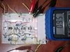
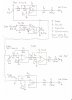
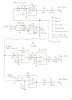
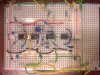
Her is the circuit I am trying to get working, but not successful.
I am seeking help with this problem. We suppose to connect a circuit with use of TL071,2 op-amps (which will be powered by +-15V) to an i-pod or some similar mp3 player with output around 1V. Now the signal is amplified and then divided into bass, middle, treble using low, band and high pass filters to light up LED for each part of the frequency (0 - 100, 100 - 1000, 1000- ... Hz).
Before the diodes I am measuring 20V AC or 10V DC which is sort of switching on and off according to the signal (which is good) so it should be lighting the LED’s. I am not quite sure what the diodes do to it although I am actually using different type from the diagram.

Thanks for any help or advice or explaining

R:)

Ps: Audioguru pls do not reply (do not waste your time by explaining basics) thanks.
 

Attachments

  • 0066 Flash01.jpg
    0066 Flash01.jpg
    3 KB · Views: 246
  • 0066 Flash 02.jpg
    0066 Flash 02.jpg
    960.9 KB · Views: 162
OK, since now you post this school project all over the internet then I will let somebody else also say that C8 should have a value that is exactly double the value of C7. Guess how?

I'll also let somebody else also say that the trimpots P2 and P3 should be removed.

I will also let somebody else explain the basics of exceeding the max allowed reverse voltage of the LEDs which is prevented with the diodes in series with them.

I will also let somebody else also say that Your circuit is biased wrongly so the output voltage from the opamps needs to be at a fairly high voltage before the LEDs begin to light.

I will let somebody else say that the circuit is missing precision rectifiers and peak detectors.

I will let somebody else say that the LEDs are missing transistor drivers.

I will let somebody else say that your teacher should have taught you all this.
 
The last sentence makes sence, but the:

I will also let somebody else explain the basics of exceeding the max allowed reverse voltage of the LEDs which is prevented with the diodes in series with them.
I will also let somebody else also say that Your circuit is biased wrongly so the output voltage from the opamps needs to be at a fairly high voltage before the LEDs begin to light.
I will let somebody else say that the circuit is missing precision rectifiers and peak detectors.
I will let somebody else say that the LEDs are missing transistor drivers.

......is the stuff i am actually trying to get "help, explanation, advice" with.

Thank you anyway R:)
 
You asked about the function of the diodes and I explained it. Do you know how a diode works and what a diode does?
Look at the datasheet for ANY LED. It says that the absolute maximum allowed reverse voltage is 5V. But the outputs of the opamps in your circuit swing down to -14V which is much too high for any LED which will destroy the LED. Therefore diodes are added in series with the LEDs so that the LEDs never have a reverse voltage.

Did you look at the datasheet for your LEDs to see how much voltage they need before they begin to light? Then if you bias the opamps so that their output voltage without a signal is slightly less then a low level signal will begin to light them and a stronger signal will make them brighter. Do you know how to bias an opamp?

Maybe next year Your teacher will teach about a precision rectifier circuit and a peak detector circuit, or you can read about them in Google today.

Did you look at how much current the LEDs need (25mA?) and look at how much current the opamps can provide (5mA)? Then you will see why transistor LED drivers are needed.
 
Hi
I get it with the diode, a bit, so i will use (1n4001 since i do not have other).
No i do not know how to bias the opamp.
Current for the LED's is indeed 25mA, i do not know how much of current can TL071 or 2 provide?
And i do not know how and where to use the transistors for driving the LED's.

I did removed the P2 P3 potentiometers,but i do not havemore of 1nF to build exactly 2nF

Thanks
 
I get it with the diode, a bit, so i will use (1n4001 since i do not have other).
A 1N4001 is bigger than is needed but it will work fine.

No i do not know how to bias the opamp.
Then your teacher did not teach the basics about opamps.

Current for the LED's is indeed 25mA, i do not know how much of current can TL071 or 2 provide?
The datasheet for the opamps shows a max voltage loss of 5V when it has a 2k ohms load, then the current is only 5mA.

And i do not know how and where to use the transistors for driving the LED's.
Then you never learned the basics about electronics.

I did removed the P2 P3 potentiometers
good. then your filters will work properly at the correct frequencies.

i do not havemore of 1nF to build exactly 2nF
1nF capacitors are available everywhere and are inexpensive.
If you are in jail then ask somebody to get two.
 
Hi there

Can anyone please help me to solve in my circuit how to ...

-Bias the op-amps
-Use transistors to drive the LED's

Thanks

R:)
 

Attachments

  • Flash lights006.jpg
    Flash lights006.jpg
    961.4 KB · Views: 120
Last edited:
Maybe next year your teacher will teach you about biasing the opamps and how transistors work.
But right now the circuit should work if you turn up its gain control and turn off the lights in the room.
Did you try it?
 
Hi there

I did try it i can see only the treble light and it is lighting slightly continuosly.

The voltages on op-amps outputs are as follows

No signal from mp3 player than (AC ) Volts on outputs of Op-amps (and at LED's)
Tl1 0V (at LED is 0.1V )
Tl2 0.4V
Tl3 0.6V (at LED is 0.8V )
Tl4 0V (at LED is 1.2V continous light)

signal from mp3 on
Tl1 0V (at LED is 0.1V )
Tl2 0.4V
Tl3 1.0V (at LED is 0.8V )
Tl4 0.2V (at LED is 1.4V continuos light)

If i measure DC voltage at LED's than i can see the change due to the sugnal from mp3-player

Thanks

Also the input from mp3-player AC 0V, DC 0.002V (cca 20mA )
 
Last edited:
Your first opamp uses P1 as its gain control. When it is turned so that its 100k is between its output and its inverting input (-) and with the 3.3k resistor to ground then the opamp has a gain of 31.3 times which is more than enough for normal music from an MP3 player to light the LEDs.

Without a signal the output DC voltages of all opamps should be very close to 0V and the LEDs should not light. Maybe the long wires on your breadboard circuit are antennas that pickup mains hum and other interference.

Look at Tl4 without a signal. Its output is 0VDC but its LED has 1.2VDC which is impossible. So there must be some AC interference causing the LED to light.
 
Every time somebody asks why his circuit doesn't work is because it was built on a breadboard.
The long wires all over the place are a mess to see what is connected wrong and they have capacitance between them and are antennas that pickup mains hum and other interference. The contacts are intermittent.

I make circuits on stripboard. The copper strips form half of a pcb and the parts and a few jumper wires form the other half. It has all holes already drilled.
I plan a compact layout. Every wire is short and soldered. Every track is cut to be as short as possible. It is easy to see all connections so there are no wiring errors. It is easy to unsolder a part and replace it. Every circuit works perfectly.
 
Hi there

Is there any chance it will work on the bread board ? Why they do them and why they want us to use them? What do the measured outputs saying in the last post with the data? Am i actualy going to get some help or advice from whole bunch of proffesionals here which will lead to some result or success?

Thanks
 
You listed voltages but did not say if they are AC or DC. One Volt is 1.0VAC or +1.0VDC or -1.0VDC, not 1.0V.
Your multimeter is made to read AC accurately only at 50Hz or 60Hz and is useless at higher audio frequencies.

Can't you see that it is impossible for the output of opamp #4 to be 0VDC when the LED it drives has +1.2VDC and lights? Where does the voltage come from?

With no signal measure and post the DC voltages at the output of each opamp. They all should be 0VDC or +0.01VDC to -0.01VDC.

Get a signal generator and feed in 50Hz at 1V and turn up the gain control a little to see the bass LED light dimmly.
Feed 400Hz and see the mid-frequencies LED light dimmly.
Feed a frequency between 2kHz to 20kHz to see the treble LED light dimmly.

Frequently a breadboard causes opamps to oscillate at a high frequency. Try adding a 0.1uF capacitor at each opamp from the Vcc+ pin to the Vcc- pin. Then connect a 0.1uF capacitor from +15V to ground and from -15V to ground near the middle opamp.

I don't see the shielded audio cable from your MP3 player to the input of your circuit but I do see a long yellow antenna wire instead that might cause feedback and will pickup mains hum and interference.
 
Hi there

The outputs of op-amps withou the signal connected are
Tl1 0VDC
Tl2 0.4VDC
Tl3 0.6VDC
Tl4 0V DC

I do not understand why is the led lighting while the voltage at TL4 output is 0VDC. Does it indicate something?

I will try to connect the 0.1uF capacitors as you saying. Is this for the oscilation of op-amps only?

I will get to signal generator tomorow first, but i will do it.

The cable from mp3 is not shielded i will try to get some.

Thanks
R
 
The output voltages of your 2nd and 3rd opamps are not 0VDC so they have problems.
Your 4th LED also has problems since its driving opamp output is 0VDC but it lights.

The 0.1uF capacitors help the opamps not to oscillate but poor wiring which has an output wire passing an input sometimes causes oscillation. The TL071 and TL072 oscillate if their output is connected to a meter or two of shielded cable due to its capacitance.

Every cable that connects a CD player or MP3 player to an amplifier is shielded. In North America they have an RCA plug at the amplifier end. Cut off the RCA plug and use the shielded cable.
 
Hi there

I am nearly done. Just one green for bass is not doing what i want :( But when i take two capacitors out than the green is plaing ok and all the time.

Thanks
R
PS i did it with the P123
 
Last edited:
Status
Not open for further replies.

New Articles From Microcontroller Tips

Back
Top