Continue to Site

Welcome to our site!

Electro Tech is an online community (with over 170,000 members) who enjoy talking about and building electronic circuits, projects and gadgets. To participate you need to register. Registration is free. Click here to register now.

  • Welcome to our site! Electro Tech is an online community (with over 170,000 members) who enjoy talking about and building electronic circuits, projects and gadgets. To participate you need to register. Registration is free. Click here to register now.

Help about project PT1000 OP amplifier -20C to 200C

Status
Not open for further replies.

Lacoxp

New Member
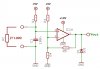
I have technical help how calculated OP Amplifier Resistors R1, R3, R4 & R5 for following:
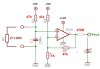
Vout(ATMEGA16 ADC or MCP3031)= 0 - 5V
PT1000 (R2) Min Resistance= 822 Ohm (-20C) and Max. Resistance=1758 Ohm (+200C).
Vcc= +10 V
Vref= +5.0V
R1 = ????
R3 = ????
R4 = ????
R5 = ????
IC1 = TLC271CP, AD621, AD620, LM358, LM324, TL071, TL072 this IC's have in CROATIA.
See Attached schematic
 

Attachments

  • PT1000_1.jpg
    PT1000_1.jpg
    105.4 KB · Views: 6,143
Your circuit has a few holes in it. First, your zener will likely burn up the op-amp or itself if you try to use it as is. You will need a resistor on the output of the op-amp to limit the current that the zener is receiving. It will also limit the current from the op-amp and generally make the circuit a bit more efficient. R3 is not necessary, remove it from the circuit. It is only complicating the calculations. If the voltage division between R1 and R2 is done well, we won't even need an amplifier for the signal, it can be sent directly to the DAC and can run off of 5V not 10V.

The maximum voltage is the higher concern so that would be with R2 at 1758 ohms. You can simply use a 1k or greater resistor for R1 and have your converter compensate for the calculations.
 
PT1000 (R2) Min Resistance= 822 Ohm (-20C) and Max. Resistance=1758 Ohm (+200C).
Vcc= +10 V
Vref= +5.0V
R1 = ????
R3 = ????
R4 = ????
R5 = ????
IC1 = TLC271CP, AD621, AD620, LM358, LM324, TL071, TL072 this IC's have in CROATIA.
See Attached schematic

hi,
Look at these values.
Keep the residual current thru the PT1000 as low as possible in order to reduce self heating.

Using the values shown, the OPA output will swing from close to zero upto ~+4.5V and the response will be non linear.

Its important that you choose an OPA that can swing close to zero output.
There are rail to rail OPA's that will work from +5V
 

Attachments

  • PT1000_1.jpg
    PT1000_1.jpg
    55.3 KB · Views: 5,786
Last edited:
Status
Not open for further replies.

Latest threads

New Articles From Microcontroller Tips

Back
Top