Continue to Site

Welcome to our site!

Electro Tech is an online community (with over 170,000 members) who enjoy talking about and building electronic circuits, projects and gadgets. To participate you need to register. Registration is free. Click here to register now.

  • Welcome to our site! Electro Tech is an online community (with over 170,000 members) who enjoy talking about and building electronic circuits, projects and gadgets. To participate you need to register. Registration is free. Click here to register now.

Help in reduce circuit losses

GH Crash

Member
Any suggestions on how to reduce the resistance of the attached circuit.

A supercapacitor (EDLC) is used to power a small motor. There is an ATTiny85 chip in the circuit that is used as a timer and a PWM controller for the motor. The problem that I'm loosing about half a volt between the capacitor's voltage and the voltage across the motor's leads. I need to minimize losses in the circuit as much as possible.

Can you suggest means to reduce voltage loses to the motor?
 

Attachments

  • PWM Circuit.jpg
    PWM Circuit.jpg
    84.8 KB · Views: 268
Thanks George, as I understand the R7 potentiometer fix the run time cutoff (10 mn) and R6/C5 is to filter the input signal from PWM motor to UC using internal ADC via Analog measurement. If you are lucky to have an oscilloscope, look at the signals on each side of R6 and you will understand what this filter is for. The PWM output frequency of Attiny85 is 490Hz, with 0 to 255 value to move PWM from 0 to 100%. Use of Schottky diode (for low Vf) and polarised capacitor should be better (10 to 47uF) but if this work it's Ok.
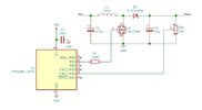
here an example of DC/DC converter using Attiny85, Mosfet, diode and Capacitor :
DC-DC_conv.jpg
 
Last edited:
R7 is a pull down resistor on the speed potentiometer. If BP is low, used stored value, if positive, then read and store value from pot.

No Oscilloscope.

I'd rather keep a discussion of the coding outside this thread. This thread deals with the physical circuit.
 
Vidal,

I’ve delayed in responding in the hopes that others would comment on your circuit design, as I am not knowledgeable enough to understand your choice of components.

I don’t understand replacing the R5 resistor in my circuit with a Schottky diode.

And, what is the purpose of replacing the R resistor with a potentiometer?
 
Hello George, sorry for you, if your circuit works like that leave it as such.
Using a Schottky diode and 10uF capacitor creates an AC signal rectifier to DC, instead of ripple at the input of the ADC, but it does not matter.
On your original schematic it was R3 a pot of 5K between +V and Gnd to provide Ref. into PB2, then you remove it by a 50-100K only to Gnd.
Out of curiosity what is the total weight of your model?
 
R6 and C5 form an RC filter. In this case, it is important that current can flow in both directiions through R6. The voltage on C5 will be a sawtooth centered on the average voltage of the point between the motor and the drain of T1. If the ADC is using Vcc as it's reference, the motor voltage can easily be calculated.

Replacing R6 with a Schottky diode changes the circuit into a peak detector.

More importantly, it turns T1, the motor inductance, D1 and C5 into a boost converter. And since, other than leakage current, there is no direct discharge path for C5, it's voltage may climb until something dies.
 
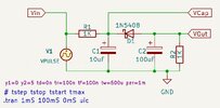
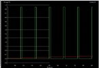
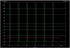
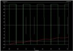
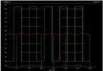
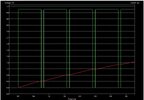
"Replacing R6 with a Schottky diode changes the circuit into a peak detector." You are right ChrisP58, this is absurd! I've made a simulation using Kicad pulse voltage source then Schottky circuit :
Test-Circuit.jpg
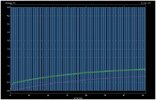
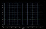
The Out signal clamp at Vf diode at 0.8V:
Full-Wave.jpgStart.jpgStop.jpg
With or without Capacitor :
Vout_D.jpgVout_10uF.jpg

George, did you know the stepper motor reference?
 
Last edited:
"Replacing R6 with a Schottky diode changes the circuit into a peak detector." You are right ChrisP58, this is absurd! I've made a simulation using Kicad pulse voltage source then Schottky circuit :
View attachment 147367
The Out signal clamp at Vf diode at 0.8V:
View attachment 147368View attachment 147369View attachment 147370
With or without Capacitor :
View attachment 147373View attachment 147372

George, did you know the stepper motor reference?
Your test circuit does not match the OP's circuit, so the results of the simulation does not give any applicable information.
 
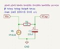
George, this is just for information, for your personal learning, your circuit is more simpler:
VCap_Sim.jpg
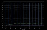
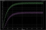
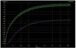
Here are the results with a duty-cycle of 10%, 50%and 90%, but again, this is just for information ...
Start-10%.jpgStop-10%.jpg
Start-50%.jpgStop-50%.jpg
Start-90%.jpgStop-90%.jpg
Good luck!
 
Vidalv

Your information is so far above my head, and the use of simplified circuits makes the results appear to be an academic study than an evaluation of a real circuit. Why not use the circuit in your Post #65?


ChrisP58's post #70 seems to indicate that there would/could be some adverse effects to the use of the Schottky diode. I don't think that I want a Schottky diode, a peak detector.

In your Post #71 you ask about a "stepper motor reference." There is no stepper motor.
 
What is the PWM frequency?

A 1K resistor driving a power MOSFET gate is a bit odd, as usually they have quite high capacitance?

It will take probably a couple of microseconds to get close to V+ or 0V at each transition, with energy losses each time.
 
The original R5 resistor (labeled R1 in the first circuit) was 1000 ohms. The present R5 is 100 ohms, as is shown in the revised circuit diagram in post #55.

JRW, the exact PWM frequency is not known, but is in the range of 500Hz.
 
Last edited:
Sorry for my absence. Life got in the way of play.

The first thing. We found a flaw in the PWM coding. In effect, it was only going to 80-85% duty cycle. That has been corrected, and now the voltage loss is now much closer to what is to be expected from the circuit.

Now it is time to see what can be done to reduce system losses. It is also where comments about circuit improvements are welcome.

Attached is the circuit diagram for the circuit as it presently exists. The big change is that a FET was added to replace the original high resistance mechanical one. The black rectangle at the top of the drawing is a connector where a stand-alone programming board is plugged in for setting the desired time and speed. (The programmer is only attached to the CMC board to adjust settings, then it is removed.) The capacitor is not part of the circuit.

I will try to respond to your last week's posts shortly
What is the purpose of C8?

Adding capacitance across the gate-drain junction of a mosfet will have a negative impact of the turnon-turnoff times.
 
Hello George, sorry for that, the circuit proposed does not match with the real need, and it's not functioning, no discharge of the capacitor (10uF) possible, the input impedance of the UC is too high. I agree with ChrisP58 no need to add a capacitor to the entry mosfet (which includes one per design)
 
"What is the purpose of C8?"

A retired electronics engineer drew up the first circuit. C8 was present in that design. When he was asked about the purpose of C*, he said it was for noise suppression,
 

Latest threads

New Articles From Microcontroller Tips

Back
Top