vne147
Member
Boncuk,
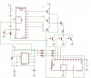
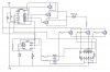
I haven't worked a lot with triacs either. I actually only used them a few times and that was all in 110 VAC applications. I kind of assumed that I could find one rated for the current/voltage requirements of this circuit. Maybe that's not the case. I just know that for the 555 timer to work properly, current has to flow both ways through the timing resistor. That's why I picked the triac. If the triac idea ended up not working the same thing could probably be accomplished with 2 transistors in parallel and their polarities reversed. The method you discussed using the motor is simpler than my idea but the original poster mentioned a 555 and a 4017. That's why I went down that path.
I haven't worked a lot with triacs either. I actually only used them a few times and that was all in 110 VAC applications. I kind of assumed that I could find one rated for the current/voltage requirements of this circuit. Maybe that's not the case. I just know that for the 555 timer to work properly, current has to flow both ways through the timing resistor. That's why I picked the triac. If the triac idea ended up not working the same thing could probably be accomplished with 2 transistors in parallel and their polarities reversed. The method you discussed using the motor is simpler than my idea but the original poster mentioned a 555 and a 4017. That's why I went down that path.