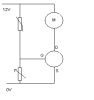
I'm building a simple fan control which only has 3 parts
NTC thermistor 10k Ω
50k Ω spindle trim potentiometer
MOSFET Power transistor (N-Channel)
The fan speed should go up as the temperature gets hotter but my fan does not turn at all.
but the funny thing is while heating up the NTC I got as high as 7.80V then it started to go back down again.
for the pot do all 3 leads need to be connected? because pin 2 (wiper) is connected to the MOSFET source and Pin 1 of the pot is connected to the MOSFET Gate.
The MOSFET drain is connected to the fan's (-) lead And the fan's (+) is connected to the NTC which runs to fan's(+)
I don't understand why it wont work
")