Continue to Site

Welcome to our site!

Electro Tech is an online community (with over 170,000 members) who enjoy talking about and building electronic circuits, projects and gadgets. To participate you need to register. Registration is free. Click here to register now.

  • Welcome to our site! Electro Tech is an online community (with over 170,000 members) who enjoy talking about and building electronic circuits, projects and gadgets. To participate you need to register. Registration is free. Click here to register now.

Help with LED switcher supply

Status
Not open for further replies.

technogeek

New Member
Hi guys,

New here, first post...

I'm looking to build an LED array. I've decided on the HV9910 switcher "buck-boost" supply. It will be powered by mains (120V) and output between 83-130V DC @ 700mA. I followed the application note for designing the circuit, but have never built a switcher before. One thing that concerns me is they wanted a 12uF cap on the output, with low ESR (tantalum or ceramic). Problem is @130V, that's at least $50 worth of caps. I plan on using a $2 electrolytic instead. I don't care if the ripple is huge or efficiency is 30% ;) But will this cause any other problems? Should I use a larger cap to make up for it?

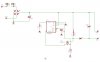
I'm attaching my circuit diagram (drawn in eagle). If you could look over it, see if anything sticks out I would greatly appreciate it. I know doublechecking my math is probably too much to ask ;)

I wasn't able to find 12uF @250V caps, so I have to use 15uF's on the input and output. I think the input cap is probably too small for the current (>1A) but there's no more space in my box so it'll have to do.

Also, ignore the part number on the central chip. I borrowed one from the atmel library so I could have a DIP socket..... obviously the HV9910 isn't in there and I didn't care to draw it.
 

Attachments

  • buckboost.jpg
    buckboost.jpg
    60.8 KB · Views: 224
use a bunch of smaller value electro's in parallel to achieve your desired capacitance .... like resistors, each one in parallel halves the esr. six 2.2 or three 4.7

you'll also want to make sure your schottky is rated for the (iirc 150% of Vout), and the switching transistor as well.

i should add ... I've seen designs implementing both parallel diodes and/or parallel fets in attempts at reducing switching losses
 
Last edited:
Is there any reason why you're using the buck-*BOOST* configuration of the circuit? PG. 6 has the main wall-outlet configuration that has reasonably sized capacitors. In the boost configuration, pin 1 of the inductor swings *up* to 2xVin meaning that that diode array is going to be exceedingly dangerous. Q1's rating is also going to need to be boosted accordingly.

Incidentally, schottky diodes in those voltage ratings are a bit on the rare side - the example schematic uses a standard fast-recovery diode...
 
Last edited:
hjames said:
Is there any reason why you're using the buck-*BOOST* configuration of the circuit? PG. 6 has the main wall-outlet configuration that has reasonably sized capacitors. In the boost configuration, pin 1 of the inductor swings *up* to 2xVin meaning that that diode array is going to be exceedingly dangerous. Q1's rating is also going to need to be boosted accordingly.

Incidentally, schottky diodes in those voltage ratings are a bit on the rare side - the example schematic uses a standard fast-recovery diode...

Yes, for the buck mode, it requires vin > 2*vout... when my vout has the potential to just about equal vin.

I'm using an ultrafast recovery diode... Or at least spec'd one.

Yes, the high voltage is something to consider. I guess to sum up your arguement, you're saying I should build 2 supplies for 1/2 the led's using buck configurations?
 
justDIY said:
use a bunch of smaller value electro's in parallel to achieve your desired capacitance .... like resistors, each one in parallel halves the esr. six 2.2 or three 4.7

you'll also want to make sure your schottky is rated for the (iirc 150% of Vout), and the switching transistor as well.

Did not know that, thanks! So what's the bad consequences of a single "high ESR" cap?

Fet and diode are rated for 400 volts
 
I'm looking to build an LED array. I've decided on the HV9910 switcher "buck-boost" supply. It will be powered by mains (120V) and output between 83-130V DC @ 700mA.
That sounds like a lot of power for LEDs (58-91 watts!). What's the spec's and part number of the LEDs and how many are you planning to power with this circuit?
 
Specs are 3 watts ea, x 40

voltage range is 2.3v-3.3V, 700mA ave max. current

I'm basically looking to build a solid state light bulb. :)
 
One last thing to persuade you *not* to use the buck-boost configuration: If the LEDs go open circuit at all, even for a fraction of a second, that inductor is going to spike to some extremely high voltage and smoke the entire circuit very fast.

If this is your first switching regulator, go ahead and try this at a nice low voltage rating first - put it on 12V DC, and watch what happens to that circuit. I'd put bets on it reaching well over 100V at the low input voltage, and sparks developing shortly before becoming a smoke generator if you plug it into the outlet.

Just have two strings in parallel with some matching resistors. Better yet, hook up two mosfets in a current mirror configuration. (Err dunno how well this would actually work...)
 
Last edited:
hjames said:
One last thing to persuade you *not* to use the buck-boost configuration: If the LEDs go open circuit at all, even for a fraction of a second, that inductor is going to spike to some extremely high voltage and smoke the entire circuit very fast.

If this is your first switching regulator, go ahead and try this at a nice low voltage rating first - put it on 12V DC, and watch what happens to that circuit. I'd put bets on it reaching well over 100V at the low input voltage, and sparks developing shortly before becoming a smoke generator if you plug it into the outlet.

Just have two strings in parallel with some matching resistors. Better yet, hook up two mosfets at the ground level of the LED strings in a current mirror configuration.

Awesome! Just the kind of info I need!

Buck config it is!

So would I need a total of 3 mosfets? IIRC the buck config used a smaller inductor too..... that would make more use of board space! I love you guys!
 
use a bunch of smaller value electro's in parallel to achieve your desired capacitance .... like resistors, each one in parallel halves the esr. six 2.2 or three 4.7
You have to be really carefull with doing this. Paralleling caps in a switcher can lead to one of them passing the majority of the ripple current and thus exceeding it's maximum ripple current rating. How much will all these LEDs cost? I would think that the cost of the LEDs will dwarf the cost of the proper caps.
Specs are 3 watts ea, x 40
voltage range is 2.3v-3.3V, 700mA ave max. current
To extend the life of your LEDs, you should run them below the max rating. Run them at the manufacturers nominal current rating. BTW, are these the type of LEDs that mount on a heatsink?
I'm basically looking to build a solid state light bulb.
For a lighthouse? :D
 
I don't know how good of an idea the current mirror thing would actually be - it was just a random idea which I haven't completely thought out. If this project is a one-off, it might be easier to just match up the diode arrays so that they have the same on voltage - bin the LEDs by voltage and wire up the LEDs so that the total voltage of both strings are the same.

The other thing to keep in mind is that these LEDs are going to generate an awful lot of heat, and LED efficiency/lifetime drops rapidly with temperature. Something of this scale (unless it is distributed over a large enough area) will need forced air cooling. At the very least the power supply and each of the LEDs is going to need to be mounted to a decent sized heatsink.

Incidentally these ratings sound a lot like the red/orange LuxeonIII's. They're in the $2 range nowadays, and something like this might be useful for Ahem. botanical reasons... http://www.dansdata.com/danletters159.htm
 
Last edited:
hjames said:
Incidentally these ratings sound a lot like the red/orange LuxeonIII's. They're in the $2 range nowadays, and something like this might be useful for Ahem. botanical reasons... http://www.dansdata.com/danletters159.htm

ha!

Actually they're cheap luxeon knockoffs (you can actually see the individual chips in the emitter.. I think luxeons use one solid hunk of Si)..... $2?? Is that in qty of 1000? I'm paying $3.50ea! Maybe they're not so cheap afterall!

PS - I guess I better cancel that mouser order until I get everything figured out
 
Last edited:
I don't know how good of an idea the current mirror thing would actually be
A constant current source is a good idea as far as efficiency is concerned. It would allow him to put more LEDs in series and not waste as much power thus creating heat which is a pain to get rid of. The danger is in the pass transistor/FET failing and blowing your expensive LEDs to heck.
Whenever I build anything that uses mains voltage I try to keep it as simple as possible. Below is a circuit of a lightbook I made for my wife. Mind you the power levels are much lower (15ma Led current) but it is pretty simple with not much to go wrong. R9 is there to limit the surge current into the cap and bridge when it is powered up. I used muliple resistors in the LED strings so I could use cheaper 1/2 watt units and spread the power dissipation around the PCB more.
 

Attachments

  • LightBook.gif
    LightBook.gif
    20.4 KB · Views: 191
kchriste said:
Whenever I build anything that uses mains voltage I try to keep it as simple as possible.

Yes!!

Exactly what I'm looking for!

I originally wanted a single transistor current source, but calculated the heat dissipated in the 30+watt range... Not cool (literally)!
 
This seems lik a wase of time and money, a compact fluroescent lamp will be a lot more efficient and give you a better quality light than an array of LEDs.
 
The 5W LEDs need a good heatsink so they don't smoke too much. The heat is about the same as a compact fluorescent light bulb. But LEDs need a current-limiting device which also gets hot.
 
The LEDs will need current-limiting circuits that also get hot.

Are you making an oven that uses LEDs and their current-limiting circuits to make the heat?
 
Status
Not open for further replies.

Latest threads

New Articles From Microcontroller Tips

Back
Top