Continue to Site

Welcome to our site!

Electro Tech is an online community (with over 170,000 members) who enjoy talking about and building electronic circuits, projects and gadgets. To participate you need to register. Registration is free. Click here to register now.

  • Welcome to our site! Electro Tech is an online community (with over 170,000 members) who enjoy talking about and building electronic circuits, projects and gadgets. To participate you need to register. Registration is free. Click here to register now.

High Power Relay H Bridge

Status
Not open for further replies.
OK, that is quite a fast opto, so it should be OK as long as the load resistance is not too high; 1K would be idea, it gives a reasonably fast recovery & makes it usable with full output up to around 5KHz, according to the data.

Note that you also need "flywheel diodes" to prevent back EMF spikes from the motor causing damage.
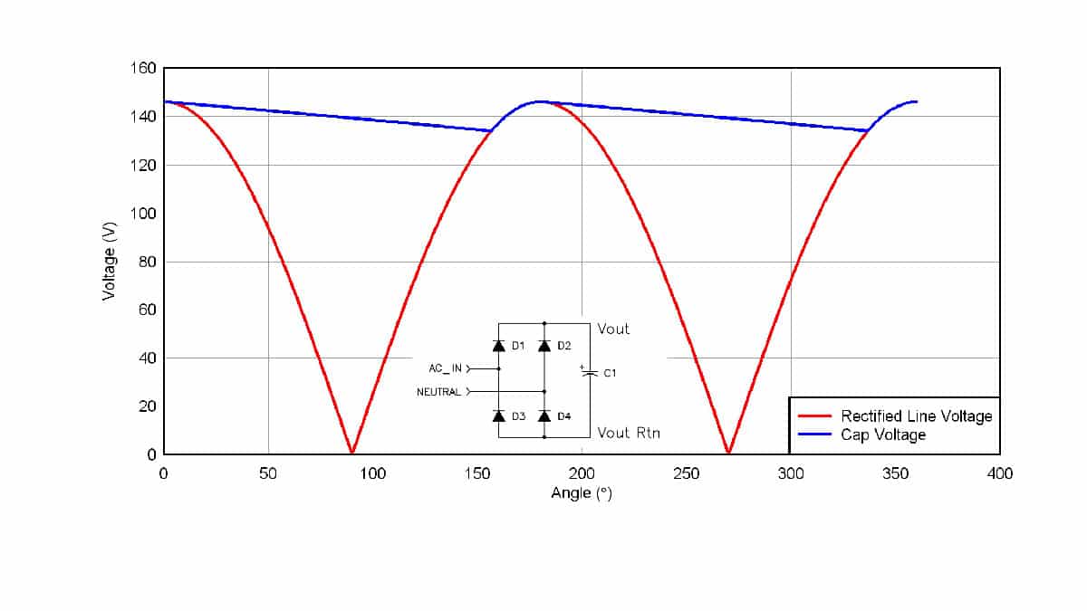
The simplest setup with an H bridge config is to use four diodes in a bridge rectifier style configuration, with the AC connections to the load (motor) and DC to the incoming supply positive and negative/ground.

Use fast recovery or schottky diodes, and make sure you have a decent size capacitor across the incoming supply, for energy recovery. Power will be regenerated from the motor if you reduce the drive duty cycle faster than the more decelerates - active braking.

(You could use a single diode between FET drain and positive power, but that would not provide protection to the relay contacts or from spikes going more negative than ground; the four diode bridge covers everything).
I also wanted to ask if fr 104 Schottky diode would work since it has a recovery time of 150ns and what type of Capacitor should i use across the incoming supply .
 
Speed-wise, any Schottky or FR diode should be fine.
The current rating needs to be at least equal to the motor full load current, whatever that is, and the voltage well above the expected working voltage.
(A typical 1N4007 can take anything up to around 30uS to turn off, which it why they are not good for much above 50/60z; they can make excellent varicap diodes though!).

Normal electrolytic caps are fine, but use ones rated at least 50% higher voltage and (in total) double or more the expected ripple current (in such as rectifier smoothing applications) for long life expectancy.

Add a ceramic or plastic film cap across the supply as well, to handle any high frequency noise the electrolytics are not good with.
 
This is now my updated circuit , i have used 0.47uF and 100nF capacitor at the power supply , plus i am using a tlp250 low side mosfet driver to drive the mosfet. I wanted to ask if the values of the capacitors i have chosen correct or not.
hbridge neat.PNG
 
Thanks for catching that Pommie, I spaced out on that one. Of course the
ESR is reflected in the minimum Z value, but it was wrong to consider the
ESR is a f(w) (to a first order approximation). Obviously we are seeing ESL
and ESC and ESR.

Kind of interesting to see, for several technologies, the "inverse Q, my term" is pretty flat
over 2 or more decades, in prior chart.

But all effects have ESR as a f(w) as follows ....

View attachment 136360

Electrode loss skin effect I believe.


Regards, Dana.
Thanks for telling me this but i dont understand the chart at all, can you explain it to me , all i know is that ESR is a resistance is which capacitors have and it should as low as possible am i right in thinking that .
 
Last edited:
Thanks for telling me this but i dont understand the chart at all, can you explain it to me , all i know is that ESR is a resistance is which capacitors have and it should as low as possible am i right in thinking that .

Don't worry about it, danadak's purpose here seems to continually post irrelevant information, presumably in an attempt to prove how clever he is?. Capacitors are VERY rarely critical - my only concern would be the ones across J1, as I can't see where it's feeding, and assuming it's power in?, 0.47uF is too small.
 
Don't worry about it, danadak's purpose here seems to continually post irrelevant information, presumably in an attempt to prove how clever he is?. Capacitors are VERY rarely critical - my only concern would be the ones across J1, as I can't see where it's feeding, and assuming it's power in?, 0.47uF is too small.
J1 is the terminal block where i will connect the battery 24v to power the motor
 
Thanks for telling me this but i dont understand the chart at all, can you explain it to me , all i know is that ESR is a resistance is which capacitors have and it should as low as possible am i right in thinking that .

You have that correct. If you take a traditional electrolytic in that chart, and compare
to a polymer tant, you get two orders or more of lower reactance, hence in a bypass
situation perform much better. More critical in precision analog situations. When
you get time Bob Pease (National Semi, now part of TI), also Analog Device's ap notes,
LTC (Jim Williams), and others have a number of comments on the importance of capacitors
and their technology limitations. Also Vishay have some excellent ap notes on Tants.

A "typical" model one can design to looks like -

1648559923535.png


"Normally" you dont have to be concerned with above unless you are doing low
noise or RF type applications.

Caps are a fascinating subject area, the ongoing development in them, the newer
technologies, the extreme problems like microphonics and soakage......

If you have been . in the business long caps fascinating in their limitations and advances.
One can always learn. The engineers at Fluke, HP/Agilent, Tek and the like also have had
many challenges and inventions in this area.

As an aside you can get a Nano VNA and investigate various properties in the AC domain.

Lastly if you use ceramics in timing applications be aware of this problem -

.https://www.digikey.com/Site/Global/Layouts/DownloadPdf.ashx?pdfUrl=863968494F2E4E13BBEA65B55A358443


Regards, Dana.
 
Last edited:
i have used 0.47uF and 100nF capacitor at the power supply , plus i am using a tlp250 low side mosfet driver to drive the mosfet. I wanted to ask if the values of the capacitors i have chosen correct or not.
I'd expect more like 1000uF or higher, plus the 0.1 ceramic or film.
The idea is to provide a reservoir of energy that can be drawn under load peaks, or stored during energy recovery, without the overall supply being affected too much by short term fluctuations.

You appear to have the diodes in the bridge backward, so they would short the supply as drawn?

I can't read the resistor values in that schematic; what is the value of the FET gate resistor?
 
Yes, but where does the little green arrow go to? - and why a 0.47uF capacitor across the supply?.
The green arrow shows the power net which will be used in the pcb schematic to make the traces for 24 positive of the battery , protues shows power net as a green arrow , as for why i used a 0.47uf capacitor it was said here in the page which said to use a 0.47uf capacitor to smooth the output for the tip250 gate driver.
tip250.PNG
 
Don't worry about it, danadak's purpose here seems to continually post irrelevant information, presumably in an attempt to prove how clever he is?. Capacitors are VERY rarely critical - my only concern would be the ones across J1, as I can't see where it's feeding, and assuming it's power in?, 0.47uF is too small.

Actually the ESR/Z graph post shows how clever other people are that invented these technologies in Capacitors.
Speaking for myself I have not invented any of that technology, how about YOU ?

"Capacitors are VERY rarely critical"

There are quite a few folks across many industries and applications that I dare say would disagree with
you. I met many engineers who could not figure out why their 10 bit, 16 bit ADCs, now into the 20 bit
capability and beyond on their processor was only showing 8 bits or less in accuracy because of a lack
of attention to generated noise left unsuppressed by crappy caps, ones they did not even consult
datasheet for their response. Poorly bypassed Vref chains and G elements in the signal path. I was
fortunate enough to learn from some of the greats in past and recent times, Pease, Williams, Siegal,
Mitra, a gent at TI I forgot his name, on analog. Most modern analog datasheets specifically have a
section on recommended bypassing, because that IS CRITICAL to performance. I was lucky enough
to do some RF work in the 70's on Ceramic caps that showed astonishingly different performance one
vendor to another. An early lesson well served in my career. 200 mV of supply rail noise on a 10 bit
or better ADC in a processor is not an achievement, its a failure in design.

On the clever scale I think I still have much to learn, and welcome it.


Regards, Dana.
 
Last edited:
I'd expect more like 1000uF or higher, plus the 0.1 ceramic or film.
The idea is to provide a reservoir of energy that can be drawn under load peaks, or stored during energy recovery, without the overall supply being affected too much by short term fluctuations.

You appear to have the diodes in the bridge backward, so they would short the supply as drawn?

I can't read the resistor values in that schematic; what is the value of the FET gate resistor?
The 0.1 cermamic capacitor you mentioned should it be 0.1uf or 0.1nf. Plus the gate resistor is 10 Ohms. As for the diodes i created them according to the generic bridge rectifier given besides it
hbridge neat2.PNG
 
Speed-wise, any Schottky or FR diode should be fine.
The current rating needs to be at least equal to the motor full load current, whatever that is, and the voltage well above the expected working voltage.
(A typical 1N4007 can take anything up to around 30uS to turn off, which it why they are not good for much above 50/60z; they can make excellent varicap diodes though!).

Normal electrolytic caps are fine, but use ones rated at least 50% higher voltage and (in total) double or more the expected ripple current (in such as rectifier smoothing applications) for long life expectancy.

Add a ceramic or plastic film cap across the supply as well, to handle any high frequency noise the electrolytics are not good with.
I also wanted to what do you mean by ripple current, does it mean it my power supply is 24v then i should use a 50v capacitor. Also the no load current of my motor was 1.2A so should using 3A 100v Schottky diodes suffice
 
Last edited:
should it be 0.1uf or 0.1nf
0.1uF, as you originally suggested.

The bridge is correct within itself, but the positive output needs to be to positive supply, for energy recovery.
As it is, all the diodes would conduct as soon as you applied power and short the whole system.

For a 24V system, I'd use caps rated at least 35V.
 
0.1uF, as you originally suggested.

The bridge is correct within itself, but the positive output needs to be to positive supply, for energy recovery.
As it is, all the diodes would conduct as soon as you applied power and short the whole system.

For a 24V system, I'd use caps rated at least 35V.
So this is the design i am thinking of making , I was thinking of using zener rated at 30v stop any transient voltage since irf540 can handle of upto 100v so it should not be a problem as for the bridge rectifier configration you meantioned could you draw a schematic or explain it to since i cant seem to understand where to place its terminals since if i place it properly then power flows from source to motor and then to ground without any pwm control which i couldn't understand. so i wanted to replace it with a zener diode would it work.
 
Yes, you can use a zener diode across the mosfet to protect it. You need to make sure that it can handle the energy that the transients will present.

Rather than a zener, I would suggest a TVS (Transient Voltage Suppressor) which is a zener like device optimized for this purpose. Again, they have power ratings that you need to select to meet your needs.

As for the diodes in the bridge, they just need to be flipped so that their cathodes are towards the positive power rail and the anodes are towards negative.
 
i cant seem to understand where to place its terminals since if i place it properly then power flows from source to motor and then to ground without any pwm control which i couldn't understand. so i wanted to replace it with a zener diode would it work.
That's what happens as you have it now...
The positive output of the bridge must go to positive power & negative output to negative power; yours is drawn the opposite way around.

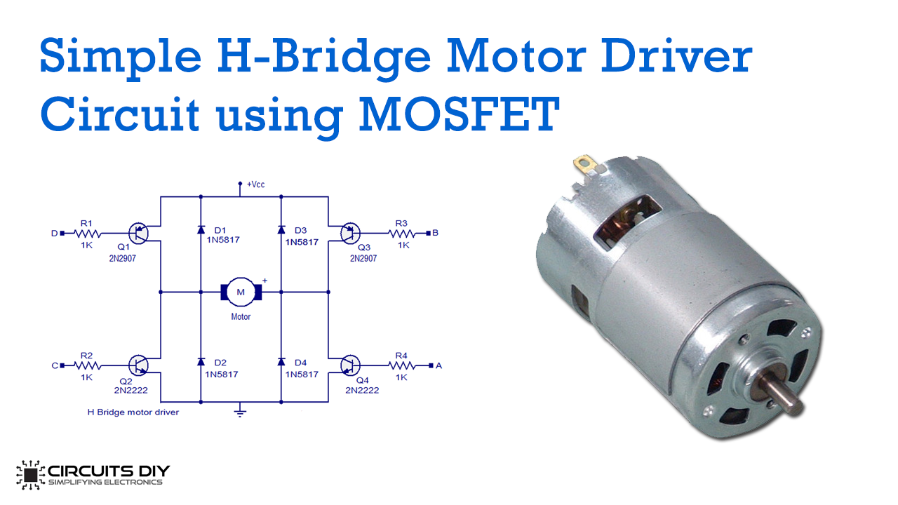
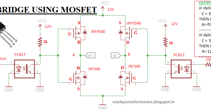
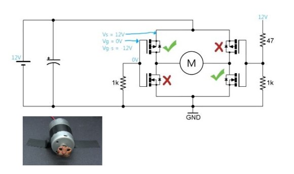
See the diodes in these examples for proper orientation - either separate diodes, or the internal ones in the FETs.
Ignore the power switching differences, just look at the diodes:


Thanks to everyone that helped me on this h bridge i will hopefully implement it in the coming days been busy with upcoming exams
 
Status
Not open for further replies.

Latest threads

New Articles From Microcontroller Tips

Back
Top