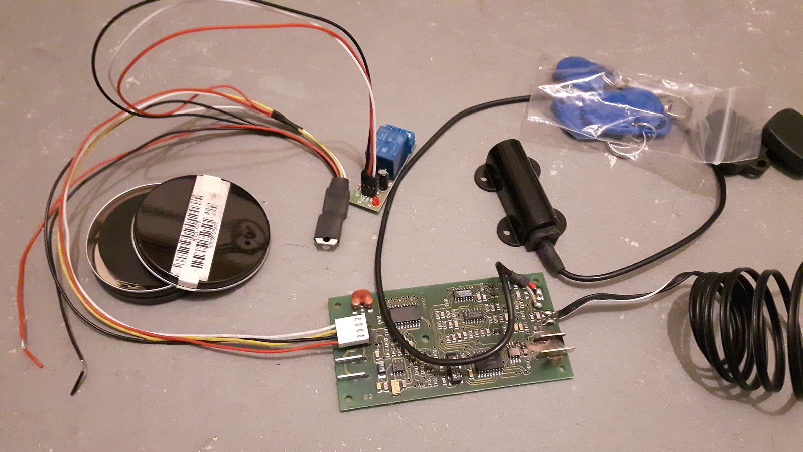
I am trying to build an escape room puzzle, where someone holds a key fob up to a sensor and a maglock opens, and I went online to buy something that I assumed was ready-in-box but instead they sent me the photo attached which I'm 99% sure was originally a car immobilizer and is now being used as a sensor with attached output. My questions is - how do I connect this to power? I have some knowledge in electrical engineering, enough to recognize most of the parts here but this is the one mystery I cannot solve. The whole thing I assume takes 12V power. Does anyone have an insight into how to give it power, or even how to set it up in general?
In photo: circuit board in the center, sensor (large, black) just off center right, attached chip up top/middle is output (for maglock), coiling wires off the right side is just a singular LED light, and included fobs are top-right. The rest is a mystery.

In photo: circuit board in the center, sensor (large, black) just off center right, attached chip up top/middle is output (for maglock), coiling wires off the right side is just a singular LED light, and included fobs are top-right. The rest is a mystery.

