Continue to Site

Welcome to our site!

Electro Tech is an online community (with over 170,000 members) who enjoy talking about and building electronic circuits, projects and gadgets. To participate you need to register. Registration is free. Click here to register now.

  • Welcome to our site! Electro Tech is an online community (with over 170,000 members) who enjoy talking about and building electronic circuits, projects and gadgets. To participate you need to register. Registration is free. Click here to register now.

i have few doubts in the temperatre monitor circuit

Status
Not open for further replies.
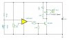
One is he wrote that RL1 mentioned in figure is the Thermistor. Are there any specifications for it? And what is all the construction he made on the diode. how to assemble it on the board. what is it exactly. and the i want to change that circuit to 9V. so i am using lmv 358 instead of ua741. Is it ok to ue or will i face any problem. And also in the circuit provided the output is shown by glowing of led. i want to change that. i output can be only 1.2V. So
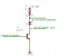
i have made a small correction in circuit. That is the second photo i have attached. will these two work..
 

Attachments

  • Temp Monitor.JPG
    Temp Monitor.JPG
    16.9 KB · Views: 264
Last edited:
2nd circuit

i was not able to add it in that msg. so i doing it here. This is the second one
 

Attachments

  • temp-1.JPG
    temp-1.JPG
    10 KB · Views: 219
Let's try this stepwise:

The thermistor is undefined. The op amp acts as a comparator. When the voltage across the thermistor is above the setpoint voltage on the 47K pot (has to be wrong, potentiometer values are 50K) the output of the op amp goes high, turns on the transistor, and that puts current through the relay coil.

The diode is a suppressor to prevent reverse voltage from the relay coil damaging the teansistor at turn off.

Provided the relay gets enough current, changing to a 9 volt supply will not affect circuit operation - unless it's a battery. Then battery life will limit operation.

A 358 is as good as the 741 for this circuit.

I am at a loss to understand the last part. If you are going to use 9 volts, why is the voltage on the transistor collector only 1.2? What kind of relay is going to operate on that voltage?
 
You didn't see the datasheet for the LMV358? Its max supply voltage is only 5.5V. It comes only in surface-mount cases. Maybe you want to use an LM358 which is a fairly normal dual opamp in an 8 pins case.

The extra transistor needs a resistor in series with its base.
 
bananasiong said:
what's the purpose of the 2.2k:eek:hm: resistor from the base to ground on the 1st picture?
It forms a voltage divider with the other 2.2k resistor and hopefully will turn off the transistor when the output of the 741 opamp goes as low as it can to about +1.2V.

The output transistors of opamps are usually darlingtons that have a 1.2V loss.
 
audioguru said:
You didn't see the datasheet for the LMV358? Its max supply voltage is only 5.5V. It comes only in surface-mount cases. Maybe you want to use an LM358 which is a fairly normal dual opamp in an 8 pins case.

The extra transistor needs a resistor in series with its base.

Sorry. Its LM358 only. Typing mistake
 
Russlk said:
The output of the LM358 goes nearly to ground, so you probably don't need the transistor. What are you trying to accomplish?

The value above the tuned value of current by 47k resistor will make the led glow. that might be working at 9V. i Want that output to be 1.2V. so i that second circuit. will it serve my need
 
Status
Not open for further replies.

Latest threads

New Articles From Microcontroller Tips

Back
Top