Electro Tech is an online community (with over 170,000 members) who enjoy talking about and building electronic circuits, projects and gadgets. To participate you need to register. Registration is free. Click here to register now.
Welcome to our site! Electro Tech is an online community (with over 170,000 members) who enjoy talking about and building electronic circuits, projects and gadgets. To participate you need to register. Registration is free. Click here to register now.
If the bulb is in the emitter lead (your drawing doesn’t indicate emitter or collector) the lamp will light after a delay. Given the nonlinear behavior of incandescent lamps, I cannot predict the luminosity verses time curve.
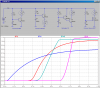
Here are four different circuits. In each, I assume that the lamp is a 9V, 10W lamp, meaning that its resistance is E^2/P = 81/10 ≈ 8Ω.
The four different configurations I tried are Common Emitter, Common Collector, Darlington, and NFET. I nominally tried to create a delay of about 1/2 sec, which is not much delay. In all cases, I tried to get the final current through the lamp close to what it would be if it the transistor is fully on. Note the timing resistor/capacitor in each case. Note that I didn't account for "resetting" the timing network for a new cycle, but that the simulation assumes that the capacitor is initially totally discharged (STARTUP directive).
I vote for the NFET version, which has the smallest timing capacitor, the largest timing resistor, the highest final current, and the best delay curve (no current until the end of the delay, then the lamp turns on quickly). The Common Collector is the worst.
The plots show the current through the lamp in the four circuits.
MikeMl, I’m afraid that your simulation has a problem. Incandescent lamps are constant current devices. As the voltage goes up, the temperature of the filament goes up and so does the resistance. The issue is that he wants a gradual increase in brightness and without knowing the luminosity verses power dissipation curve for the lamp to be used, it cannot be predicted.
Jbelectric777, Get the lamp you intend to use and a photo meter (possible the exposure meter in a camera) and plot a brightness curve from say 1 watt to 10 watts. It is then possible to plot a voltage/brightness curve. At that point, we should be able to come up with a circuit that will track your needs. Depending on how much control and if the change in brightness has to be linier, you may have to go to a phase control system.
MikeMl, I’m afraid that your simulation has a problem. Incandescent lamps are constant current devices. As the voltage goes up, the temperature of the filament goes up and so does the resistance. The issue is that he wants a gradual increase in brightness and without knowing the luminosity verses power dissipation curve for the lamp to be used, it cannot be predicted...
This site uses cookies to help personalise content, tailor your experience and to keep you logged in if you register.
By continuing to use this site, you are consenting to our use of cookies.